

USB connector endUSB连接端
The USB-form end provides a device connection boundary, with end orientation and lead routing arranged for the installation space.USB形式的端头可作为设备接入边界,端头朝向与引线走向按安装空间布置。
USB- and LC-form ends appear within the same combined connection piece. Their shapes identify interface forms, while the functional connection still needs a circuit definition.USB形式端头与LC形式端头出现在同一组合连接件中,端头外形提供的是接口线索,不能替代功能电路定义。
The combined ends provide a starting point for routing different connection paths together. Define optical, power and other signal functions and acceptance separately; a combined form does not establish optical-electrical conversion.组合端头用于讨论不同连接路径的共同布置。光通道、电源与其他信号的功能及验收分别定义,不凭组合外形推断光电转换。
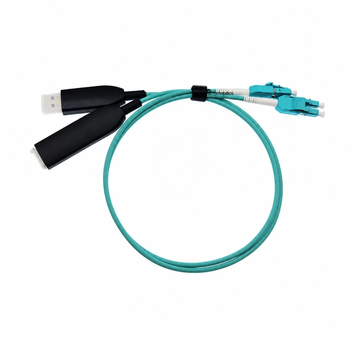
The USB-form end provides a device connection boundary, with end orientation and lead routing arranged for the installation space.USB形式的端头可作为设备接入边界,端头朝向与引线走向按安装空间布置。
The assembly organizes a transition or combined connection, with end directions, transition sections and fixing arranged around the equipment positions.组件以转接或组合形式组织连接,可围绕两端设备位置安排端头方向、过渡段与固定。
Confirm optical and electrical ends, maps and acceptance references separately, then coordinate the trunk, branches and labels.光接口与电接口的端头、连接表和验收依据分别确认,再统一安排主干、分支与标识。
The table describes the construction and available configuration choices. Materials, dimensions, circuits and inspection requirements are agreed for each project.以下说明展示结构与可配置内容。具体材料、尺寸、电路和检验要求按项目确认。
| USB and LC interface formsUSB与LC两类接口 | Provide full interface documents, mating direction and intended task for the USB and LC ends. End names do not establish a protocol or conversion function.分别提供USB端与LC端的完整接口资料、插合方向与使用任务,不能由端头名称直接推定协议或转换功能。 |
|---|---|
| Interface functions and internal arrangement接口功能与内部结构 | Use a block diagram to define USB-side power or data, LC-side optical channels and any active module. Record each path and its acceptance separately.按功能框图确认USB侧供电或数据用途、LC侧光通道及是否包含有源模块;各路径的定义和检验分开记录。 |
| Optical-channel mapping光通道对应 | Confirm LC channel positions, fiber type and the remote equipment requirements. USB contacts are not a direct contact map for optical channels.确认LC端通道位置、所选纤型与对端设备要求;USB接点不直接作为光通道的针位对应关系。 |
| Length and breakout datums长度与分支基准 | Define measurement points, tolerances and identification positions for the overall cable, fine tails or individual branches. Allow enough length for equipment mating and removal.明确总长、端部细尾段或各支路的测量起止点、公差及标识位置,并保留设备插拔所需余量。 |
| Hybrid routing and protection混合布线与保护 | Arrange trunks and breakouts around fiber bending limits, electrical insulation and end retention. Define jackets, shielding and strain support for their respective paths.围绕光纤弯曲边界、电路绝缘要求和各端头固定位置安排主干与分支,分别确认护套、屏蔽和应力支撑。 |
| End-face and optical acceptance端面与光学验收条件 | Agree end-face cleanliness, channel checks and any required optical test conditions, limits and reporting responsibility at project start for the selected interface and cable configuration.在项目开始时约定端面清洁、通道核对及所需光学测试条件、限值和报告责任,并对应所选接口与光缆配置。 |
The following directions cover equipment connections and distribution routes. Define optical interfaces, channels and optical acceptance from the specific system documents.以下连接方向围绕设备与配线路径展开。所选光接口、通道及光学验收要求以具体系统资料为依据。
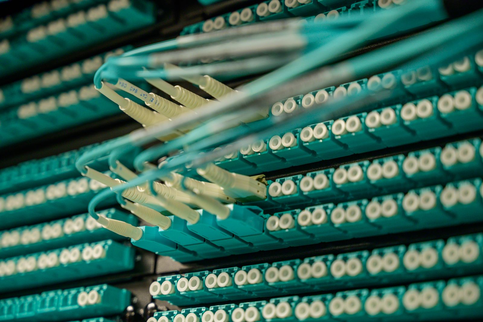
At fiber-distribution panels, arrange connector orientation, boot clearance and service allowance around port positions. Confirm the connector series, end-face form and channel identification against the distribution record before defining each jumper.光配线面板的跳接需按端口位置安排端头方向、尾套空间与可拆卸余量。接头系列、端面形式和通道编号与配线记录一起确认。
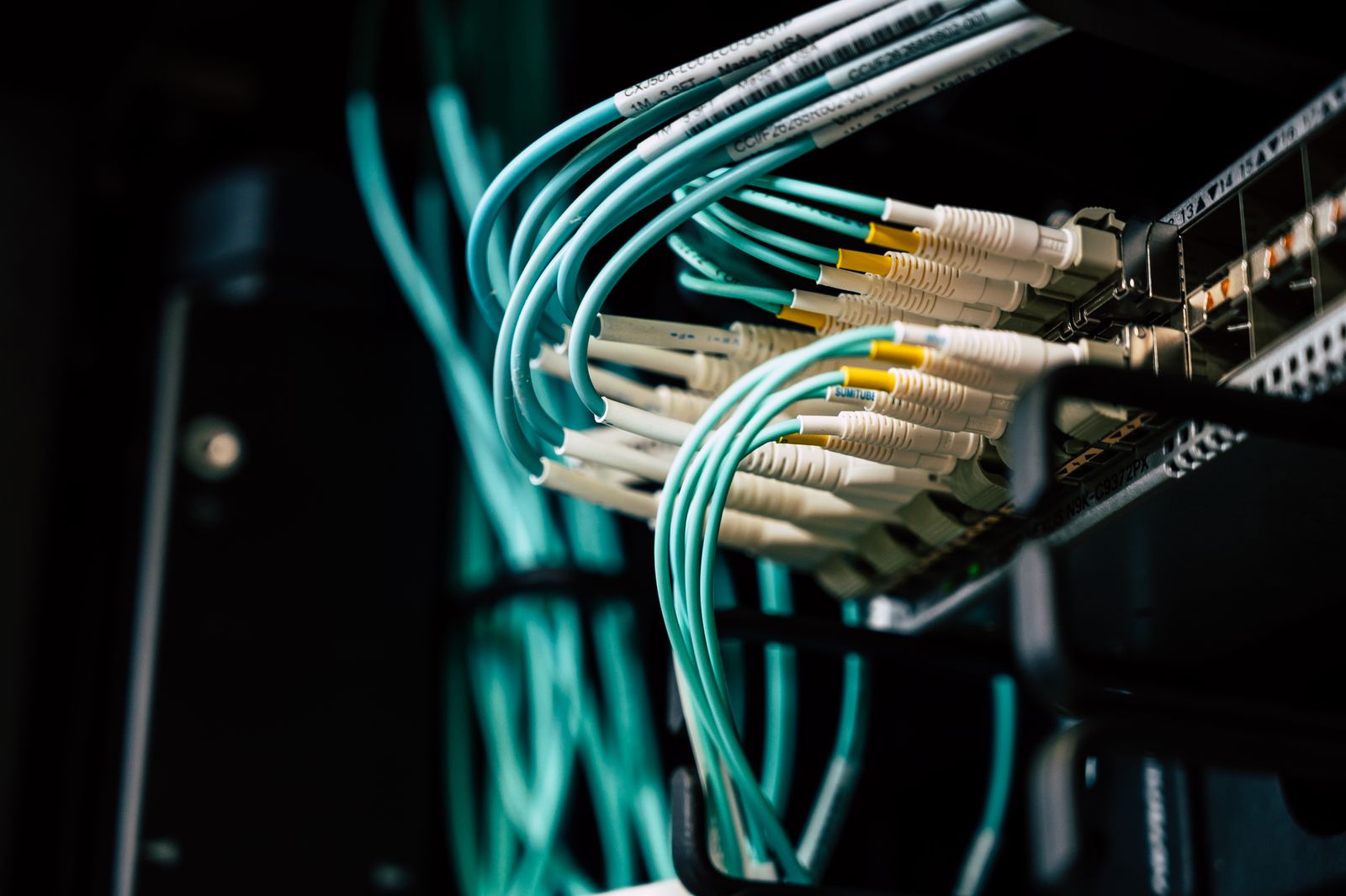
For short links between equipment optical ports and the distribution side, review mating ends, transmit/receive direction and bend clearance. Use equipment-port documents to establish channel mapping rather than inferring it from housing colors.设备光口与配线侧之间的短距离连接,重点是端头对插、发送接收方向和弯曲空间。通道对应以设备端口资料为准,不用外壳颜色推断。
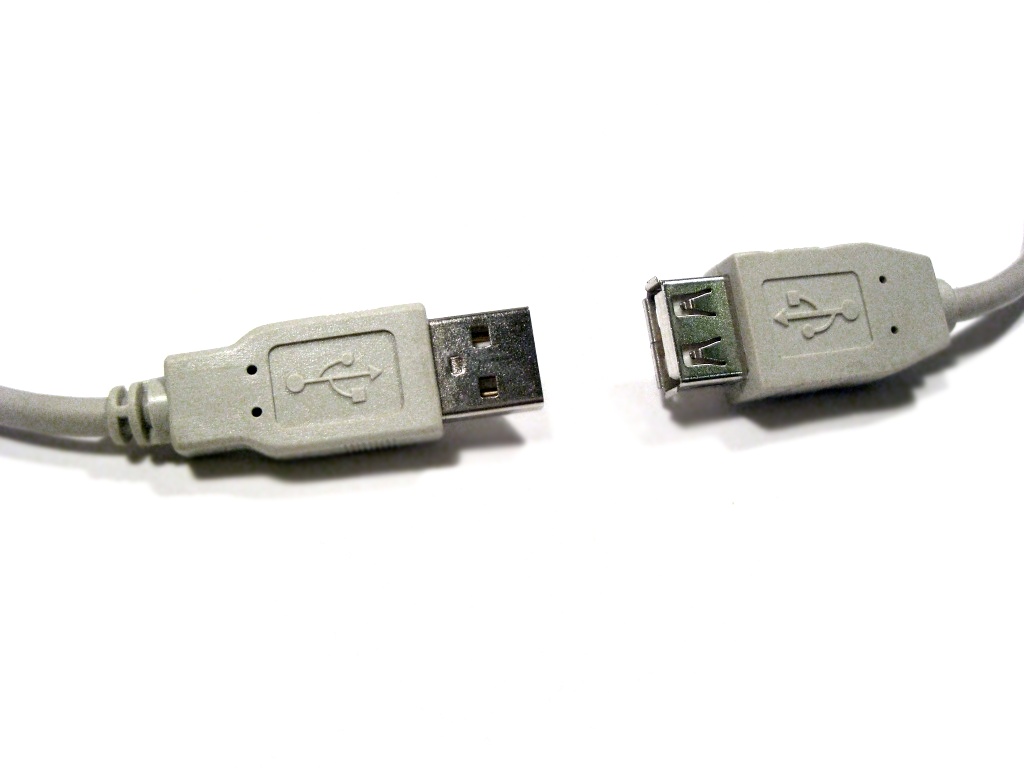
Where a project needs a USB-form interface, define its power, service or data task before arranging mating access and routing. Define the LC optical interface separately; the two end forms do not establish USB transmission over fiber.如项目需要USB形式接口,先明确其供电、维护或数据任务,再安排壳体插拔和线缆走向。LC光接口单独定义,不能按两端外形默认实现USB信号的光传输。
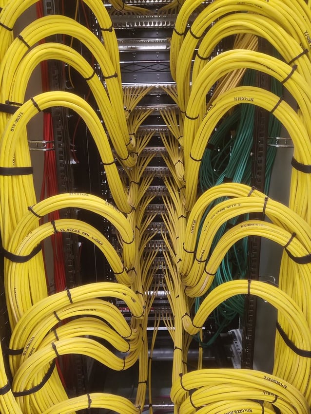
Vertical cabinet routes need space for turns, supports and servicing. Use the selected optical cable documents to set bending and tensile limits, and keep stored slack separate from equipment airflow and removable-module access.竖向布线路径需要为转弯、固定和维护留出空间。按所选光缆规定弯曲与拉力边界,并将余长收纳位置与设备风道、可拆模块分开安排。
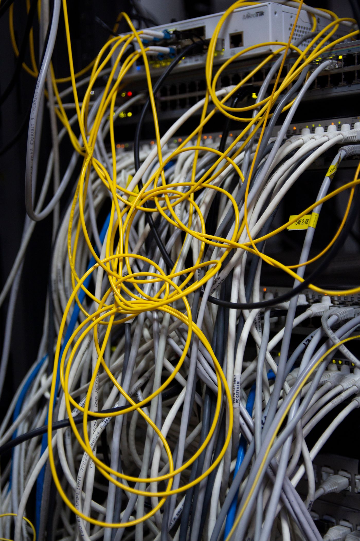
When cabinet modules use different interfaces, coordinate end positions and labels in one assembly drawing. Retain separate maps for optical channels, power and other signals so each connection purpose can be checked during installation.机柜内模块使用不同接口时,可在装配图中统一安排端头位置与标签。光通道、电源及其他信号仍各有对应表,安装人员能够逐路核对连接用途。
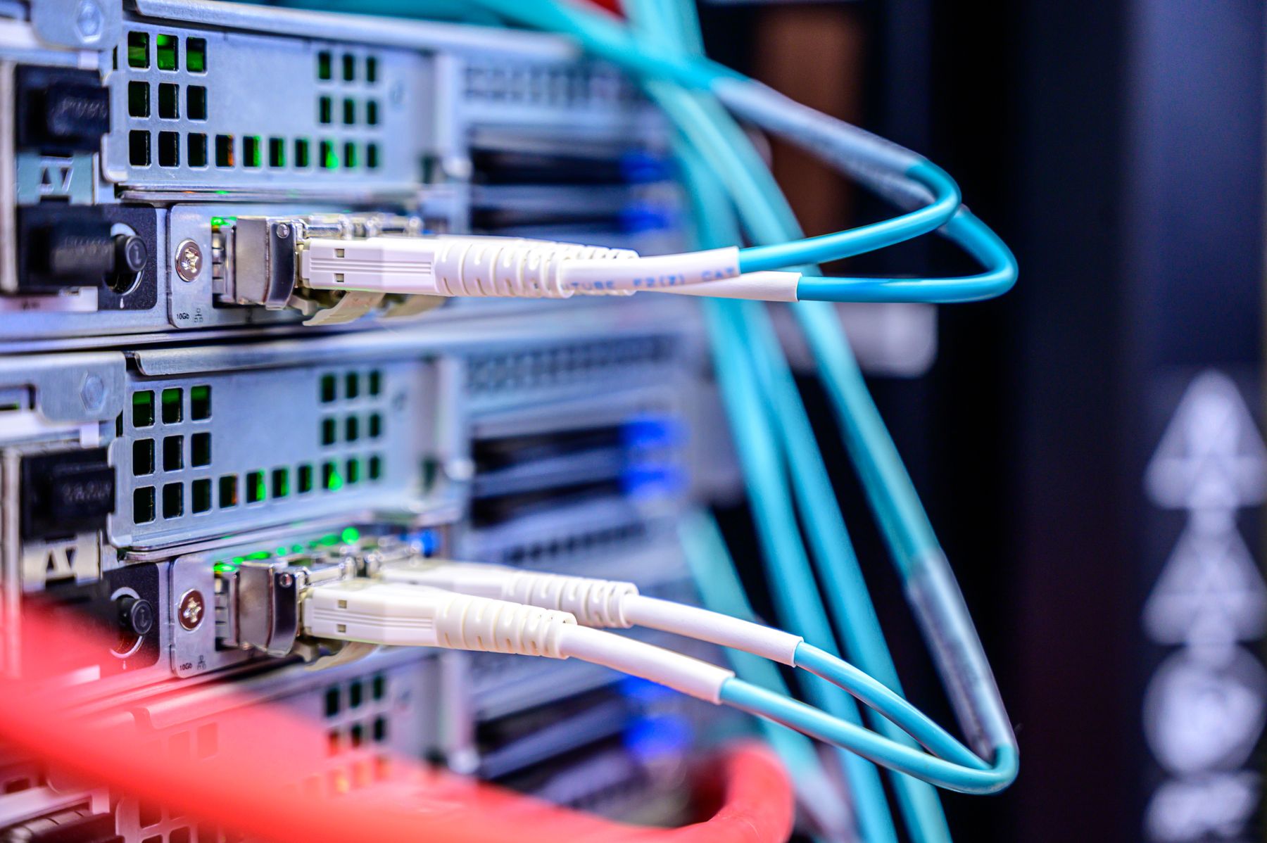
Combined connections around optical modules need defined module interfaces, auxiliary supply and responsibility for each cable section. Review the sample layout and functional documents before defining optical and electrical acceptance within the complete system plan.光模块周边的组合连接需明确模块接口、辅助供电与各段线缆的责任边界。样品先核对连接布局与功能资料,再按完整系统方案确定光学和电气验收。

Our China factory provides custom wire harness manufacturing and OEM/ODM project support. For projects involving optical connections, define electrical manufacture, optical materials and termination, installation assembly and optical acceptance as separate scopes before agreeing samples and delivery documents.Super Smile-Tech中国工厂提供定制线束制造与OEM/ODM项目支持。涉及光连接的组合需求,分别确认电连接制造、光纤物料与端接、安装装配及光学验收的执行范围,再确定样品方案与交付文件。
Create optical-channel and power or other signal maps from equipment documents. Define each end function before combining them in an assembly drawing and identification plan.以设备资料分别建立光通道映射、电源或其他信号连接表,明确各端头用途,再整理为统一的装配图与标识方案。
Set overall length, fine-tail length, breakout positions and jacket sections around the rack route. Include supports, bending limits and service allowance in the approval drawing.围绕机架路径调整总长、细尾长度、分支位置和护套段落,并把固定、弯曲与维护余量写入确认图。
Use the sample stage to review interface assembly, channel records and installed dimensions. Agree the scope for optical termination, optical testing and reports on the specific project.样品阶段分别确认接口装配、通道资料和安装尺寸;光纤端接方式、光学测试与报告要求按项目商定范围执行。
They do not. Equipment block diagrams and circuit documents must establish the interface functions. If the project includes an active conversion module, define its supply, protocol and validation scope separately.不能这样判断。需要设备功能框图与电路资料确认各接口用途;如果项目含有源转换模块,其供电、协议和验证范围必须另行定义。
Create a map from end-port views, transmit/receive definitions and channel IDs. For MPO or breakout structures, also specify polarity and branch order in the acceptance records.用两端端口视图、收发定义及通道编号建立映射。MPO或分支结构还需约定极性与分支排序,并在项目验收记录中体现。
Provide USB and LC equipment-interface documents, a functional block diagram, optical-channel and power or data requirements, and target lengths. Confirm any active module and each path function before sampling and acceptance planning.提供USB与LC接口的设备资料、功能框图、光通道及供电或数据要求、目标长度。先确认有无有源模块和各通道任务,再讨论样品与验收。
Share the equipment block diagram, optical interfaces and channel map, power or other signal maps, and trunk and branch dimensions to define the mixed assembly and validation scope.提供设备功能框图、光接口和通道表、电源或其他信号连接表,以及主干与分支尺寸,明确混合连接的装配和验证边界。