


Harness design
What should sample acceptance check?
Define dimensions, terminal retention and electrical checks before approval.
Read the key points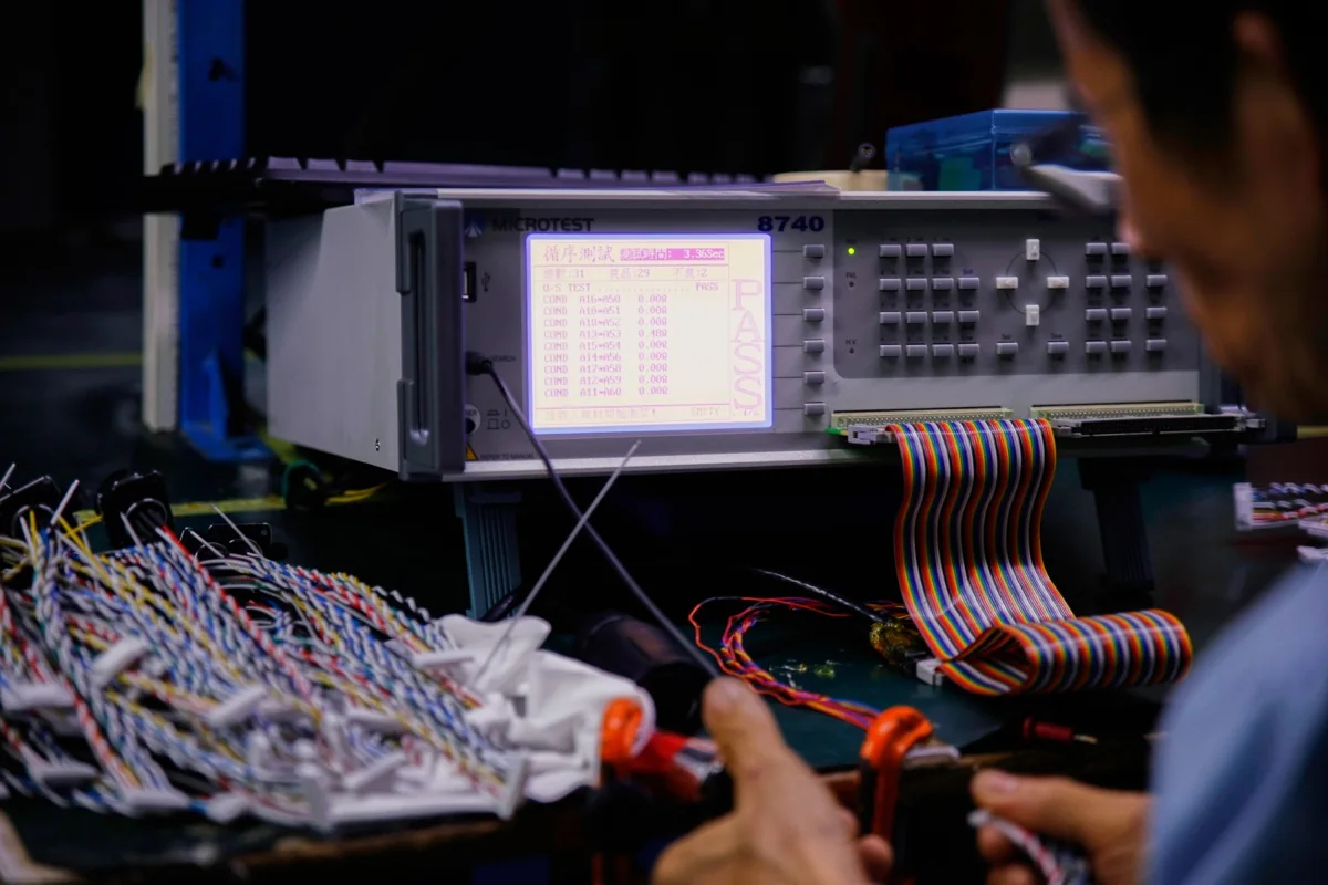
Drawings, connector selection, cable materials and manufacturing choices for your next custom assembly.
15 practical questions about interfaces, materials and manufacturing. Select a question to read the key points.
Define dimensions, terminal retention and electrical checks before approval.
Read the key points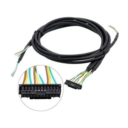
Compare the mating face, latch, cavity count and dimensions.
Read the key points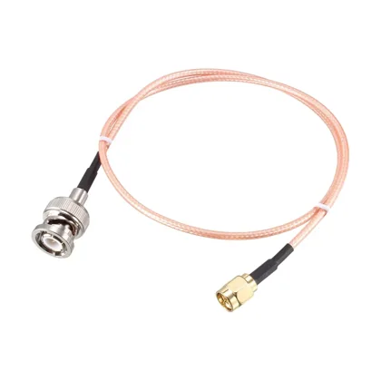
Check impedance, frequency, loss and length as well as interfaces.
Read the key points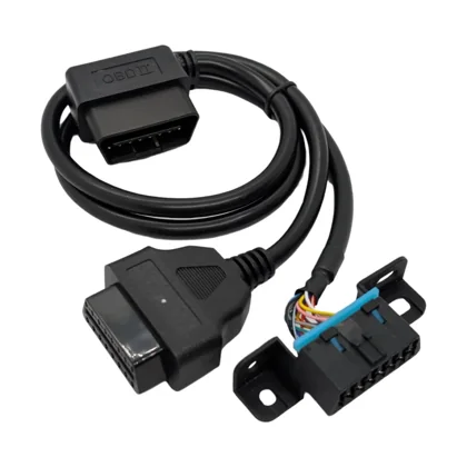
Review bus loading, power and tool behavior before simultaneous use.
Read the key points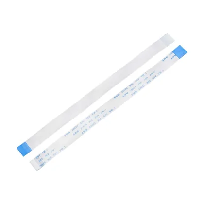
Show both contact faces, pitch and insertion length on a defined view.
Read the key points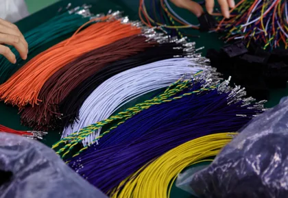
Use one identification scheme and map every core to its connector pin.
Read the key points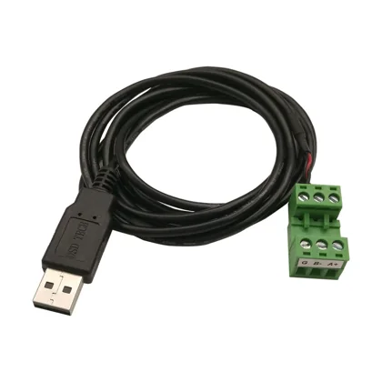
Specify the interface version, intended function, device definition and cable length.
Read the key points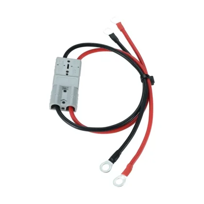
Specify the hole, orientation and mounting reference to avoid forced twisting.
Read the key points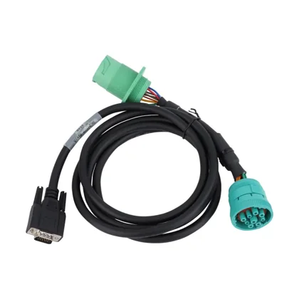
Verify the series, keying, pin assignment and tool requirements.
Read the key points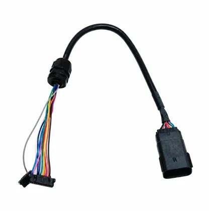
Check the cutout, panel thickness, fixing method and seal position together.
Read the key points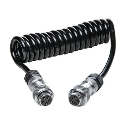
Distinguish relaxed length, working extension and the straight end sections.
Read the key points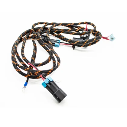
Compare protection against abrasion, heat, bending and service needs.
Read the key points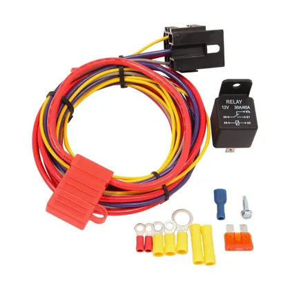
Review wire protection, startup current and the fuse time-current behavior.
Read the key points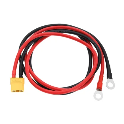
Provide continuous and peak current, length and installation conditions first.
Read the key points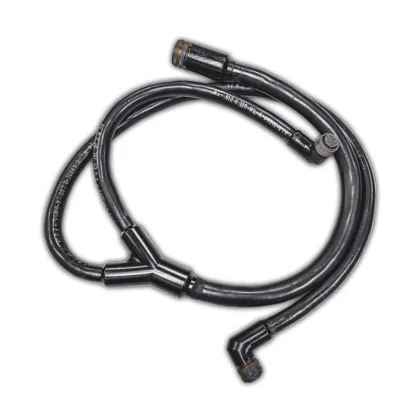
Review pulling, repeated bending and exposure before defining tail protection.
Read the key pointsChoose a topic to expand its questions. Each answer opens separately.
120 questions across 6 topics
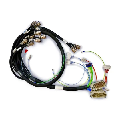
Define branches, pinouts and installation limits before quotation and sampling.
Send mating-face and side photos, overall and branch dimensions, equipment purpose and expected quantity. A sample helps establish construction; pin functions and hidden connections still need confirmation.
Related products & engineering notesDefine connector and terminal part numbers, the pin map, wire sizes and colors, length datums and tolerances, branch positions, labels and protection. Keep the drawing revision and acceptance criteria aligned with the approved sample.
Related products & engineering notesStraight-line distance does not capture the full cable route. Allow for bends, fixing points, access for mating and service slack, and state the connector datum used to measure each length.
Related products & engineering notesList appearance, dimensions, terminal retention, pin-to-pin continuity and agreed electrical tests. Passing continuity confirms the tested connection paths; equipment-level functional validation remains a separate check.
Related products & engineering notesChoose a clear datum, such as the mating face, housing rear or terminal end, and state the tolerance. Drawings and inspection fixtures should use the same measurement rule.
Related products & engineering notesState the hole size, orientation relative to the branch and relationship to the mounting surface. Add a side view where needed, and check insulation coverage and tool access without forcing the wire to twist.
Related products & engineering notesSet tolerances around installation space, fixing points and mating access. A short branch between fixed interfaces may need tighter control, while a longer route may require deliberate assembly slack.
Related products & engineering notesSpecify temperature, fluids, cleaners and abrasion exposure, together with the printing method and required identification life. Check legibility and attachment on samples as well as confirming that the label text is correct.
Related products & engineering notesDefine which conductors connect electrically, their sizes and the expected branch currents. Specify the joining method, splice position and insulation; identical branch counts do not establish identical internal connections.
Related products & engineering notesCompare abrasion, temperature, bending and service needs, then check the finished bundle diameter. Local contact points may need extra protection even when the rest of the harness is fully covered.
Related products & engineering notesPlace fixing points to support harness weight and pulling loads while preserving mating access and natural bends. The spacing depends on connector backshell construction, harness stiffness and the equipment layout.
Related products & engineering notesCheck terminal seating, locking features and retention according to the connector assembly instructions. A partly seated contact can move backward during mating even when the housing exterior appears normal.
Related products & engineering notesDistinguish a physical crossing from an electrical splice and mark relevant branch directions, front-to-back relationships and installation datums. Add a local detail or installation photo where a flat drawing leaves the route ambiguous.
Related products & engineering notesProvide enough slack for disconnection and service without creating contact with moving parts or tight bends. Confirm where the slack sits on the installed route rather than simply increasing overall length.
Related products & engineering notesInclude the part number, quantity, installation position and orientation of clips, grommets or fixing accessories supplied with the harness. Agree who supplies and installs each item to avoid omissions during sampling or equipment assembly.
Related products & engineering notesReview current switching, signal type, shielding and grounding before combining routes. Where needed, change grouping, separation or shielding and verify the result in the equipment rather than relying on appearance.
Related products & engineering notesIdentify the sample and drawing revision, then mark the affected branch, measured dimensions and equipment interference with installation photos. Distinguish a drawing deviation from a changed requirement before agreeing the revised construction.
Related products & engineering notesAssess how a material change affects mating, crimping, dimensions, electrical behavior and environmental performance. Update the BOM and revision, then agree which checks must be repeated before production approval.
Related products & engineering notesConsider tooling, programming, setup, testing and supplier minimum packs as well as wire and connector prices. Sharing expected repeat quantities helps compare practical production options for a small initial order.
Related products & engineering notesProtect latches, exposed contacts, sharp ring terminals and molded tails, and avoid tight coiling. Choose packing around harness weight, bending limits and the way the assembly will be handled on arrival.
Related products & engineering notes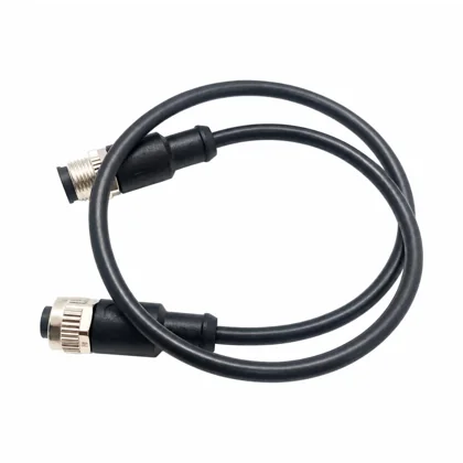
Specify the complete assembly through its interfaces, signal path and strain protection.
Check the pin map, power routing, shield termination, cable construction and intended function. Assemblies with identical-looking plugs may carry different signals, so connector shape alone is not a purchasing specification.
Related products & engineering notesSpecify how the shield connects to a shell or ground terminal, the treatment at each end and system grounding constraints. Review the termination construction together with the equipment EMC design.
Related products & engineering notesConsider tail protection where a cable sees pulling, repeated bending or environmental exposure. Confirm cable diameter, jacket material, installation space and tooling before defining the molded geometry.
Related products & engineering notesProvide the interface version, required data function, length, shielding and device-side definition. State the method for any impedance or transmission testing; connector shape and continuity do not establish full data performance.
Related products & engineering notesList the cavity-to-cavity connections at both ends, including the viewing directions and unconnected positions. Terms such as straight-through or crossover can be ambiguous, so production and testing should reference the same pin table.
Related products & engineering notesAssign clear end identifiers or equipment-side names and use them consistently in drawings, labels and test documents. If the assembly is directional, mark its installation direction rather than relying on how the cable is laid out.
Related products & engineering notesBackshell clamps, seals and molded entries are designed around a cable diameter range. Use the specific cable data or measurements; an unsuitable diameter can compromise retention, assembly or sealing.
Related products & engineering notesProvide a suitable transition beyond the plug and follow the cable bending limits and strain-relief design. Repeated bending concentrated at the termination can damage conductors or the connection over time.
Related products & engineering notesIf the design requires shield-to-shell bonding, list that path and its acceptance criteria in the test plan. Conductor continuity does not verify the shield connection, and shell continuity does not replace equipment-level EMC validation.
Related products & engineering notesWhere a resistance limit is required, define measurement endpoints, circuit scope, temperature and method, including test-lead and contact effects. Passing a continuity check does not establish compliance with a specified low-resistance limit.
Related products & engineering notesIdentify positive and negative on the center contact, outer contact or numbered positions, and state the viewing direction. Wire colors and a generic plug description do not replace an explicit polarity map.
Related products & engineering notesA drain wire is one shield-connection method. Its suitability depends on frequency, termination length and system grounding; confirm whether circumferential shell contact is required rather than treating any ground wire as equivalent.
Related products & engineering notesDefine permitted flash, parting lines and surface defects in the drawing or appearance standard. Review mating, latch and mounting areas separately, because acceptance should consider the effect on assembly and use as well as appearance.
Related products & engineering notesTooling defines the external shape, parting surfaces and cable exit. Reusing an existing mold requires checking connector dimensions, positioning and molded wall geometry; a finished-product photo is insufficient for that decision.
Related products & engineering notesConfirm nominal impedance, frequency range, allowed loss, length and connector termination construction. Review requirements across the complete link, because matching connector names alone do not establish suitable RF performance.
Related products & engineering notesSimple continuity does not reveal every pairing or transmission problem. Verify pair assignments, termination sequence, length and the intended Ethernet performance, then use the appropriate test method for the application.
Related products & engineering notesA USB connector shape does not establish data capability. Confirm the connected conductors, interface version, power requirements and device roles, then specify the assembly around its intended function rather than a generic USB label.
Related products & engineering notesChanging length can affect loss, timing and noise behavior. Review the interface, cable construction and equipment requirements, because a working short sample does not validate the same construction at every longer length.
Related products & engineering notesDefine the moving section, fixing points and permitted bending zone so motion occurs where the cable is designed to flex. Review tail retention and strain relief together to limit loads at contacts.
Related products & engineering notesContinuity checks connection paths, while insulation or withstand testing assesses separation under stated conditions. Functional testing addresses equipment behavior. Define methods and acceptance limits separately because these checks establish different things.
Related products & engineering notesIdentify the vehicle, controller and task before reviewing interfaces and protection.
Provide the vehicle or equipment model, year, diagnostic-tool model, photos of both interfaces and the pin definition. A mechanical fit does not confirm the power path, communication protocol or function.
Related products & engineering notesIdentify the full controller model, connector orientation, power and ground pins, communication lines and intended operation. Use the correct revision of a reliable pin reference and verify the wiring before connection.
Related products & engineering notesMap temperature zones, vibration, fluids, abrasion points and fixing locations before selecting wire, seals and sleeving. One connector temperature rating does not define the operating limit of the complete harness.
Related products & engineering notesActuators and calibration tools may use similar housings with different pin functions and wiring directions. Confirm the full model, mating-face photos, an existing sample and the control equipment before defining the cable.
Related products & engineering notesModel year, options, market version and controller generation can change interfaces or wiring. Provide precise vehicle details and existing harness references instead of using the model name alone to confirm compatibility.
Related products & engineering notesColor can help identification, but verify the series, keying, pin assignment and tool requirements. Similar nine-position housings do not by themselves establish the correct power routing or communication connections.
Related products & engineering notesConfirm the vehicle supply range and the diagnostic tool input limits, then verify the harness power path. A passive mechanical adapter does not convert voltage or make an incompatible power input suitable.
Related products & engineering notesA splitter provides connections but does not guarantee simultaneous operation. Review bus loading, termination, tool behavior and power capacity, then validate the actual combination of vehicle, splitter and diagnostic devices.
Related products & engineering notesBranch length, data rate and network topology affect signal integrity. Review the vehicle bus and tool connection method; extending a cable changes more than its pin-to-pin continuity relationship in the network.
Related products & engineering notesThe need for termination depends on the existing network and connection position. An extra resistor changes bus loading, so confirm the vehicle and tool configuration before deciding whether the adapter should include one.
Related products & engineering notesConfirm whether the diagram shows the controller or harness side, then check latch orientation, keying and molded cavity numbers. Verify the exact controller reference rather than copying a similar connector diagram.
Related products & engineering notesSpecify permanent supply, ignition control, grounds, fusing and the external power connection for bench use. Follow the controller requirements for voltage and operation rather than simply duplicating the vehicle connector arrangement.
Related products & engineering notesControllers may distinguish power grounds, signal grounds and shield connections. Follow the specific pin documentation and system grounding scheme; labels that mention ground do not automatically authorize joining those conductors together.
Related products & engineering notesA cable establishes the specified electrical connections; it does not perform actuator calibration. Follow the particular actuator and control-equipment procedures for settings, position learning and validation after replacement or repair work.
Related products & engineering notesMark sections that move with the engine and those fixed to the body, then define their transition, slack and fixing points. Check relative movement during installation validation to avoid contact loading or repeated rubbing.
Related products & engineering notesCheck hole size, panel thickness, edge condition and harness movement before selecting a grommet or bulkhead arrangement. Define abrasion protection and sealing separately, and prevent wire contact with sharp edges during installation.
Related products & engineering notesCheck the replacement wire insulation diameter, terminal compatibility and seal range, then inspect the seal after removal. Equal conductor sizes do not guarantee equal diameters, and reuse must follow the applicable repair instructions.
Related products & engineering notesAvoid placing splices in repeated bending zones, water traps or high-abrasion locations. Allow space for insulation and installation, and select the position against the vehicle layout and repair requirements rather than convenience alone.
Related products & engineering notesConsider wire protection, startup current, circuit length, ambient temperature and the fuse time-current characteristic as well as normal load current. Review the fuse, holder and harness together as one power circuit.
Related products & engineering notesWire colors can vary with vehicle version or previous repairs. Cross-check the correct pin reference, cavity position and circuit function; use color as an identification aid rather than the sole wiring definition.
Related products & engineering notes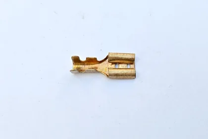
Review the housing, terminal, seal and mating half as one system.
Photograph the mating face, sides, latch and rear entry, then add cavity count, pitch, dimensions and visible markings. Color and outline narrow the search; a mating half or original part number helps confirm the choice.
Related products & engineering notesA connector family may use different terminals, wire sizes and seals. List the complete matched set in the BOM, including the terminal conductor range and the seal cable-diameter range.
Related products & engineering notesCompare mating dimensions, keying, terminal construction, locking and retention, materials and environmental requirements, then validate the proposed substitute for the project. A similar outline or family name does not prove interchangeability.
Related products & engineering notesMatch the terminal, wire and crimp tooling. Confirm stripping, crimp height, pull-force and visual criteria against the applicable terminal application specification and project documents; one set of values does not fit every terminal.
Related products & engineering notesSuffixes may identify differences in keying, plating, color or packaging within a family. Quote the complete manufacturer part number and provide the drawing revision and mating part so a similar-looking number is not selected by mistake.
Related products & engineering notesState whether the pin map is viewed from the mating face or wire entry. Show a latch or key as the datum; the two views can appear mirrored. Assembly and inspection should use the same numbered view.
Related products & engineering notesNaming can differ between connector families. Identify whether the contacts are pins or sockets, then supply the housing part number and mating part. This avoids selecting an interface by the housing outline alone.
Related products & engineering notesCompare keying, polarization, latches and mating depth as well as pitch and cavity count. Similar-size families may use different coding. Check the manufacturer drawings against the actual mating part before approving the selection.
Related products & engineering notesCheck the terminal conductor range and insulation support range separately. Seals also depend on insulation diameter. Supply the wire specification and actual outside diameter as well as AWG so the complete termination can be reviewed.
Related products & engineering notesCheck the contact materials and finish requirements on both mating sides against the operating environment. Record plating as a separate substitution check, using the applicable family documents to decide whether a proposed change is acceptable.
Related products & engineering notesInclude retainers and secondary locks in the parts list and define their installed positions. Assembly documents should specify terminal seating checks and locking sequence; a closed housing alone does not confirm that every contact is correctly retained.
Related products & engineering notesCheck the connector family instructions for unused cavities, including the specified plugs or sealing arrangement and installation positions. Use the matching parts and review the finished assembly against the agreed sealing test conditions.
Related products & engineering notesShow mating access, latch operation and the cable route after the exit. Mark an angled connector orientation on a defined view, then check the sample in its installation position for clashes and cable bending clearance.
Related products & engineering notesProvide the panel cutout, thickness, fixing method, threads and seal position as well as the mating interface. A panel drawing or section view helps establish whether the connector can be installed and secured as required.
Related products & engineering notesAssembly current capacity also depends on wire size, ambient temperature, loaded circuits and heat dissipation. Provide operating current and duty conditions, then review the connector and wire documents for the proposed installation.
Related products & engineering notesDescribe the expected mating frequency, access and whether disconnection occurs under load. Check the chosen family specifications for operating limits and mating durability; connector size and housing material do not establish those values.
Related products & engineering notesSpecify the manufacturer, full part number, quantity, packaging and traceability documents needed. Raise lot, date-code or document requirements during quotation so availability and the information supplied can be confirmed before purchase.
Related products & engineering notesPackaging affects tooling, feeding method and material allowance. Keep packaging suffixes in the requested part number and confirm the quantity unit. Prices per contact, bag and reel need a common basis before comparison.
Related products & engineering notesRecord the approved part number, applicable revision and validation result in the controlled BOM. State whether mixed use is allowed and how parts are identified. Additional substitutions require a separate review against that approved configuration.
Related products & engineering notesCheck whether contact removal is permitted, which extraction tool is required and what reuse restrictions apply. Describe field-service needs during selection so the repair procedure follows the chosen connector family instructions.
Related products & engineering notesDefine space, movement and environment before choosing molding, joining and shielding.
Identify the encapsulated parts, material limits, geometry and sealing needs, then review resin, temperature, pressure and tooling. A process name alone does not establish suitability for every connector, PCB or cable jacket.
Related products & engineering notesCheck the mated condition, cable entry, seal fit, branches and molded areas. A protection rating must match the complete construction and agreed test conditions; a component rating does not automatically apply to the full assembly.
Related products & engineering notesDefine branch wire sizes, conductor materials, splice relationships, current paths, splice positions and insulation protection. Review the joining process and validation criteria for the actual conductor combination.
Related products & engineering notesStart with the connector system, pitch, contact orientation, circuit count and routing, then compare bending and termination requirements. The term ribbon cable does not mean the end construction or assembly method is the same.
Related products & engineering notesDefine overall overmold length, maximum diameter, cable exit and equipment interfaces. Allow access for mating and latch operation. Dimensioned drawings provide a usable basis for tooling review and sample inspection alongside appearance references.
Related products & engineering notesReview adhesion, molding conditions and subsequent flexing using the actual resin and jacket combination. Confirm material grades, then include the interface seal and strain relief in the validation plan for the proposed assembly.
Related products & engineering notesProvide the component layout, connection faces, test points, permitted coverage and material limits. Mark keep-out areas and tooling contact positions on the drawing, then inspect those areas on the molded sample before approving the construction.
Related products & engineering notesDefine assembly condition, closure of interfaces, test medium, exposure conditions and acceptance criteria. Reference the same test document for samples and production so “waterproof” is supported by an agreed, repeatable method.
Related products & engineering notesA splice changes local shape and stiffness. Review the joint position together with fixing points and cable movement, allow room for insulation protection, and evaluate the sample using the intended routing and installation.
Related products & engineering notesSpecify insulation material, coverage, separation from adjacent conductors and securing method. Match the protection to joint dimensions and operating conditions, then define visual checks and any required electrical inspection in the acceptance documents.
Related products & engineering notesShow the exposed contact face at each end on a flat diagram, with pitch, circuit count and insertion length. Check the diagram against both mating connectors so orientation terms do not lead to an incorrect order.
Related products & engineering notesDefine stiffener position, length, thickness and orientation relative to the contacts. Check the mating connector requirements because stiffeners affect end thickness and seating; pitch alone does not confirm a suitable FFC interface.
Related products & engineering notesMark the colored edge, pin one and the viewing direction for every connector, including any reversed or branched section. Verify the first assembly against the pin map instead of inferring all connections from the colored edge.
Related products & engineering notesCheck cable pitch, conductor size, insulation dimensions and the connector approved wire range. Confirm tooling and assembly requirements for the chosen cable; a similar appearance is not enough to approve another ribbon construction.
Related products & engineering notesShow shield continuity, joining and termination at each branch, including connections to shells or ground terminals. Review the breakout as part of the system shielding design and check that the proposed construction can be assembled.
Related products & engineering notesProvide end fixing points, available space and assembly movements. Review whether cable loads reach the small contacts, then agree strain relief with the connector and fine-wire termination requirements and check the sample in its installed position.
Related products & engineering notesCheck backshells, hardware, shield termination and cable bending space as well as mating dimensions. Review the equipment section with the complete connector configuration so the compact interface can be installed without clashes behind the connector.
Related products & engineering notesReview tooling construction, internal cable routing and equipment clearance when the exit changes. Record the revised dimensions and applicable version, then agree which sample checks must be repeated before the revised assembly enters production.
Related products & engineering notesPull tests, cross-sections or teardown checks may consume samples. Agree the inspection items, sample quantities and records before sampling, and distinguish assemblies intended for installation checks from those reserved for process examination.
Related products & engineering notesDefine retracted length, working extension, straight-tail lengths and connector orientation, with the mounting and movement pattern. Check the sample for restoring action and equipment clearance throughout its agreed working range rather than relying on a fully stretched length.
Related products & engineering notesTurn electrical, movement and environmental needs into a cable specification.
Compare conductor material, stranding, insulation, temperature and voltage ratings, outer diameter and applicable standards as well as size. Review current capacity against bundling, ambient conditions and installation.
Related products & engineering notesA soft feel does not establish continuous-flex or torsion capability. Specify the motion, travel, speed, bend radius and life target, then select a cable rated for those operating conditions.
Related products & engineering notesList temperature, fluids, abrasion, flexing, installation dimensions and marking needs, then compare datasheets for specific cable part numbers. A material name is an initial filter, not a complete cable specification.
Related products & engineering notesThey describe different material properties and validation requirements. State the relevant standards, classes, temperature conditions and required documents separately; one property does not establish the others.
Related products & engineering notesThe same conductor area can use different strand constructions. Supply strand count, individual strand diameter or a complete wire part number, then review termination and installation requirements for that construction.
Related products & engineering notesAWG describes conductor size; insulation material and wall thickness can still differ. Match seals and insulation support to actual outside diameter, and recheck those interfaces whenever the wire construction changes.
Related products & engineering notesProvide continuous and peak current, duty, supply voltage and permitted voltage drop, along with length, bundling and ambient conditions. Review wire sizing together with circuit protection, terminals and the equipment requirements.
Related products & engineering notesCable length and circuit resistance affect voltage at the load. Check the complete outgoing and return path against operating current and permitted load voltage when selecting conductors for a longer power connection.
Related products & engineering notesReview operating voltage, insulation system, applicable standards and installation environment. Distinguish cable ratings from assembly test requirements, and agree any dielectric test conditions separately rather than deriving them from rated voltage alone.
Related products & engineering notesReview actual temperature, contact conditions, exposure duration and limits of the other assembly materials. Include connectors, tubing and jackets in the assessment, and identify local heat sources on the intended cable route.
Related products & engineering notesState whether the cable must move, bend or be handled at the minimum temperature. Check the specific cable conditions, then validate the required movement; a soft feel at room temperature does not establish cold-flex performance.
Related products & engineering notesIdentify the actual oil or cleaner, concentration, temperature and contact duration, then compare the specific jacket data. A material name or an oil-resistance statement does not establish suitability for every chemical exposure.
Related products & engineering notesCheck fixed-installation and repeated-motion bend requirements separately, including where bending occurs. Allow room at connector exits, clamps and cable-chain entries, using the applicable cable documents to establish the permitted radius.
Related products & engineering notesProvide chain space, the cable combination and end fixing arrangements. Follow the chain and cable instructions for layout and movement allowance, then check the full travel for crowding, pinching or added tension in the installed sample.
Related products & engineering notesSelect shield construction with the signal type, equipment shielding design, movement and termination space in view. Specify drain wires and end connections so the cable structure and assembly termination can be reviewed together.
Related products & engineering notesRecord circuit pairing, colors and termination pins together to prevent split or mixed pairs during assembly. For signal-sensitive connections, agree the cable construction and checks required by the selected interface and protocol.
Related products & engineering notesUse a single color table or core-number scheme and map each conductor to its connector pin. Where colors repeat, specify extra numbering or identification and check the first assembly against the actual cable markings.
Related products & engineering notesReview termination method, conductor material requirements and service environment, including the applicable terminal instructions. When conductor finish changes, use the project documents to decide which process checks and sample approvals need repeating.
Related products & engineering notesState the manufacturer, wire part number, applicable standard and required supporting documents in purchasing requirements. Compare cable markings with the supplied records at receipt. A wire approval does not automatically certify the finished assembly.
Related products & engineering notesCompare conductor construction, insulation diameter, materials, ratings and applicable standards, then check terminals, seals and processing conditions. Record the approved substitution scope in the change documents so conductor area is not the sole acceptance criterion.
Related products & engineering notes
Send the information you already have. We can review the remaining details with you.
A sample, interface photos and equipment details can provide a starting point for review. Before sampling, confirm pin functions, dimensions, materials and requirements that cannot be established from the sample itself.
Identify the valid drawing and BOM revisions and flag differences from samples or email instructions. Resolve conflicting requirements before approval, then use the agreed document set as the basis for quotation and manufacture.
Explain confidentiality and permitted use before sharing drawings. Discuss an NDA where required, then provide the information needed for review. Sensitive details can be shared in stages under the agreed document-handling arrangements.
Supply the current drawing, quantities for samples and production, and original-part or alternative-part requirements. Include special inspection, packaging and delivery conditions so the quotation scope can be established with fewer missing assumptions.
Send the complete manufacturer part number, quantity and document requirements, stating whether you need loose parts or an assembled product. Availability, sourcing, packaging and supporting records must be confirmed for the specific request.
A brand or part number identifies the selection target. Review mating interfaces, construction, materials and project validation requirements before approving an alternative. The accepted configuration then becomes the basis for procurement and manufacture.
Mark sourcing requirements against each BOM item, identifying mandatory original parts and items open to alternatives. Check the proposed part numbers during quotation and sample approval, and record the permitted scope of any change.
Link the approved sample to its drawing revision, BOM and inspection requirements, including any accepted deviations. Use that agreed record for production and document verbal changes before they alter the manufacturing baseline.
Timing depends on complete requirements, material supply, tooling and inspection arrangements. State the required date and priorities so a practical schedule can be agreed after review and reassessed when construction or materials change.
List development samples, validation samples and expected production quantities separately, with the anticipated ordering pattern. This helps review material packaging, tooling allocation and delivery arrangements for the actual project.
List part numbers, quantities, packaging, inspection documents and expected arrival dates in advance. Agree suitability, incoming checks and material allowance before processing so supplied-part issues can be addressed before the assembly schedule is set.
Define the tooling purpose, applicable product revision, cost scope and management requirements. Raise modification, storage or ownership conditions during quotation and include the agreed terms in the project documents.
Start with the approved drawing and use conditions. Agree continuity and any insulation, dielectric, mechanical or functional checks, including methods and limits. Plan equipment-level validation separately from assembly inspection.
Specify required document names, formats and batch references during quotation so the available scope can be confirmed. Records depend on the materials and supply source; agree requirements before purchase and production.
Provide label text, position, customer part number and revision, plus unit-pack, carton and scanning requirements. For barcodes, send the coding rule and a sample layout so the artwork can be checked before use.
Clarify whether the quotation includes products, tooling, packaging and transport, with the delivery location and applicable trade terms. Confirm payment and dispatch conditions before comparing offers with different delivery scopes.
Provide the old and new revisions, changed items and treatment of delivered or in-process goods. Review material, tooling and inspection effects, then agree costs, schedule and the batch where the new revision takes effect.
Reference the previously approved customer part number, revision and sample record, and state whether anything has changed. Confirm quantity, timing and material status rather than relying on assumptions from an older email chain.
Retain the affected sample and packaging. Provide the part number, batch, quantity and clear photos with operating conditions and expected behavior. Include wiring and equipment details when the issue appears during installation or use.
The links below knowledge answers lead to relevant product categories with example assemblies and engineering notes. Share the closest example with the changes you need to help describe interfaces, construction and operating conditions.
Use these notes to prepare project requirements. Materials, performance, processes and acceptance criteria depend on the specific parts, drawing and application.
Share your drawing, part number or sample information. We can review the interfaces, construction and project requirements with you.