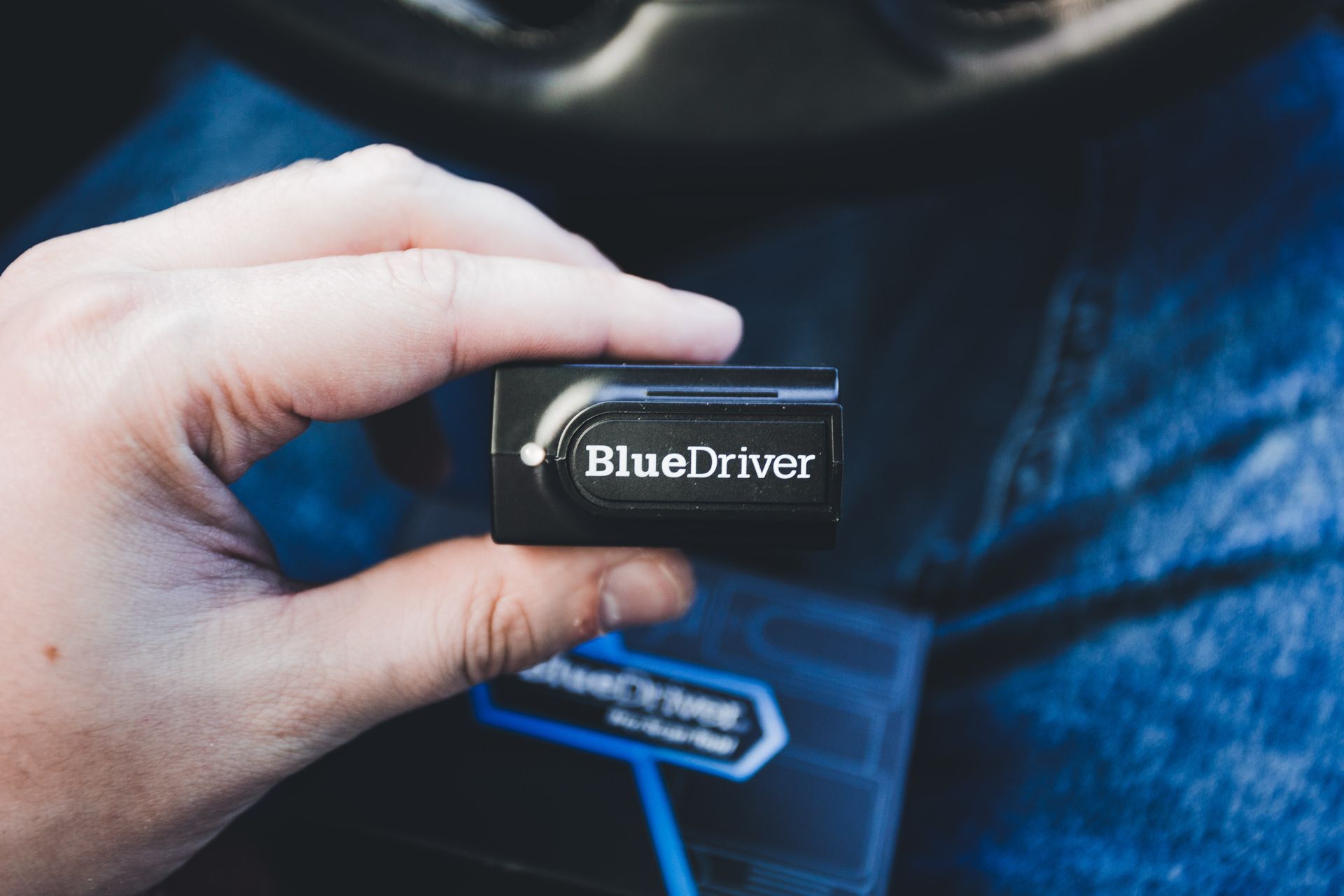
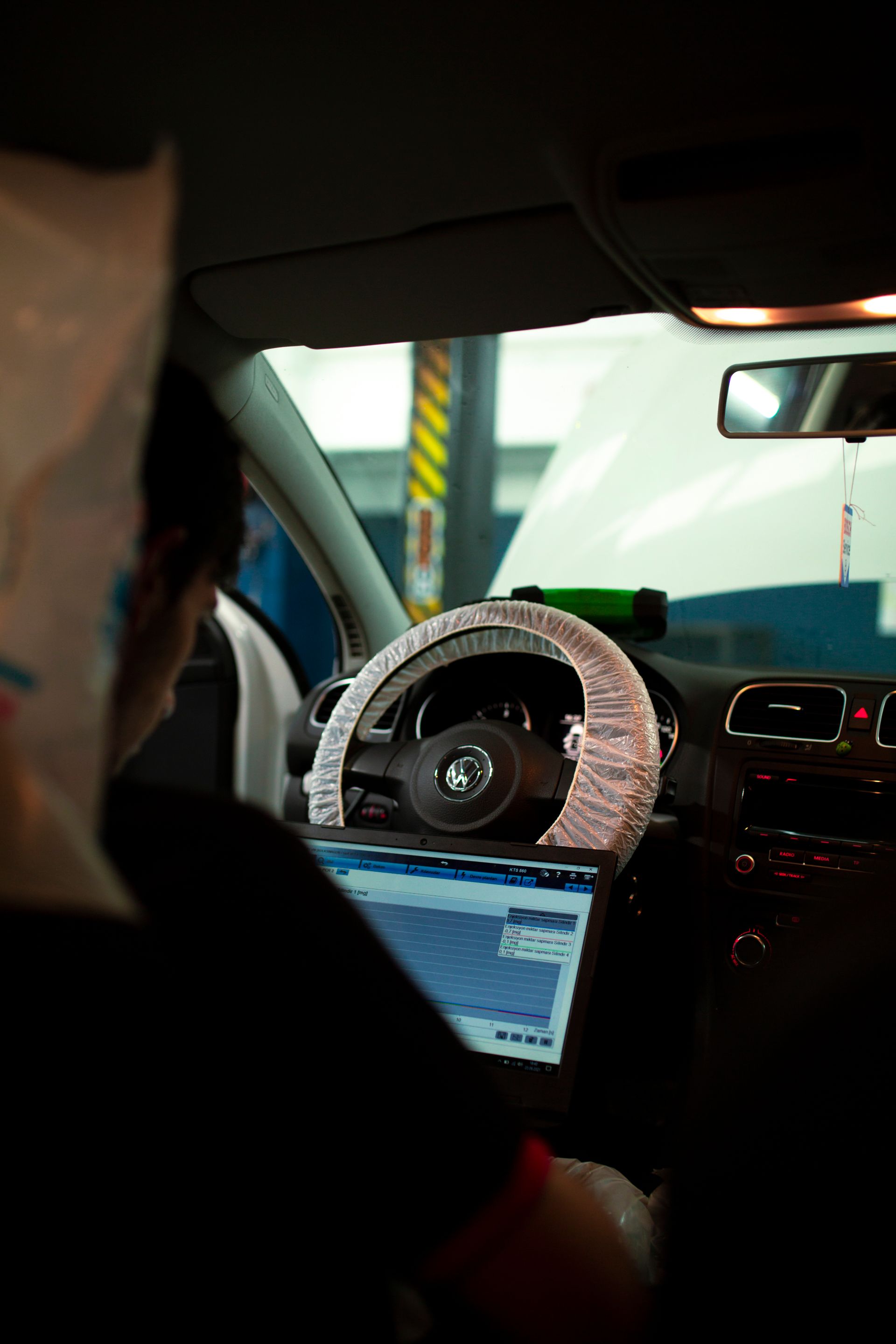
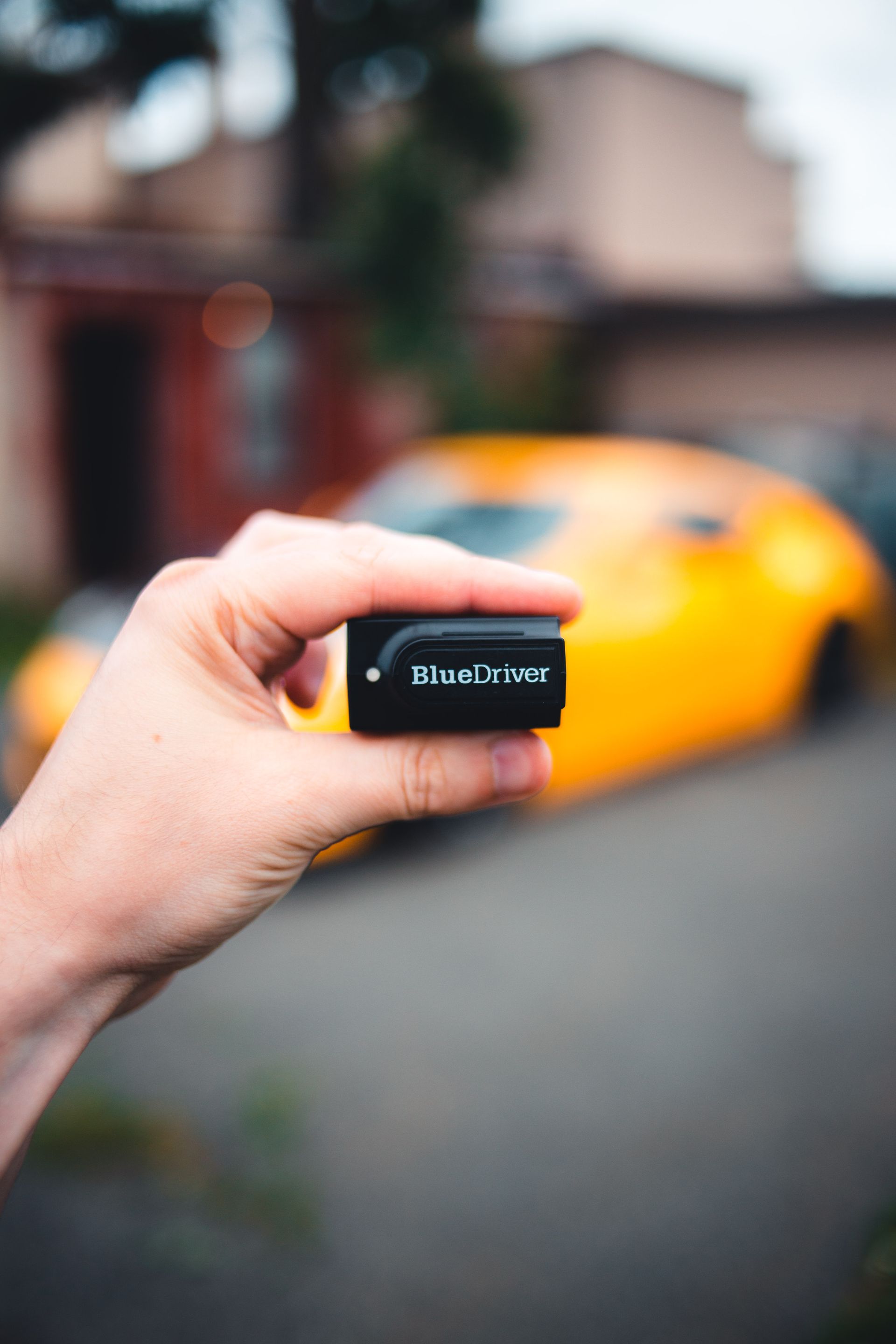
Automotive diagnostic and OBD harnesses connect a vehicle diagnostic link connector to scan tools, vehicle communication interfaces, data loggers, telematics devices, test fixtures and service adapters. The category includes short extensions, right-angle leads, Y splitters, legacy-vehicle adapters, DB-style interfaces, RJ45 or USB-side assemblies and custom equipment tails; connector shape alone does not define pinout, protocol, power path or intended duty.
Build the Harness Around the Diagnostic Task, Not the Connector Shape
One 16-position shell may carry regulated diagnostic contacts, manufacturer-discretionary circuits, power, grounds and several possible physical layers. A dependable assembly begins with the vehicle, task and device, then controls every conductor between them.
16CANKVCI
01
ASSEMBLY FAMILIES
OBD is a broad assembly family, not one universal extension lead
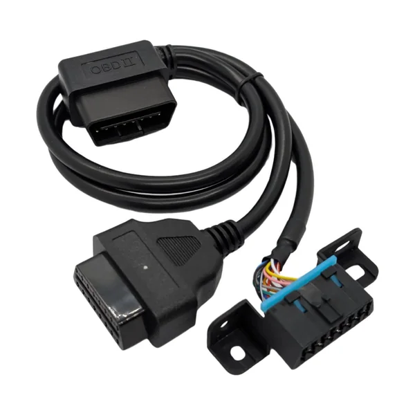
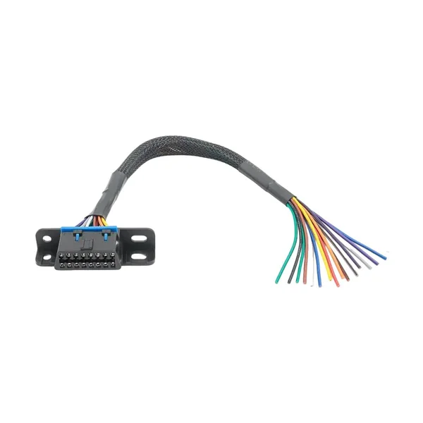
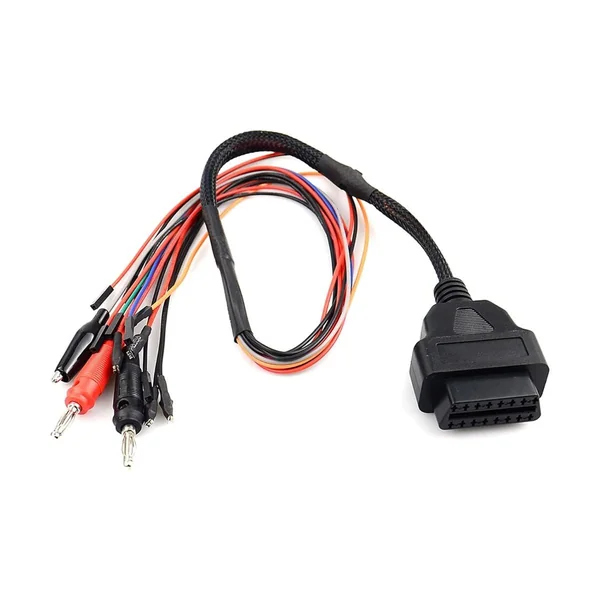
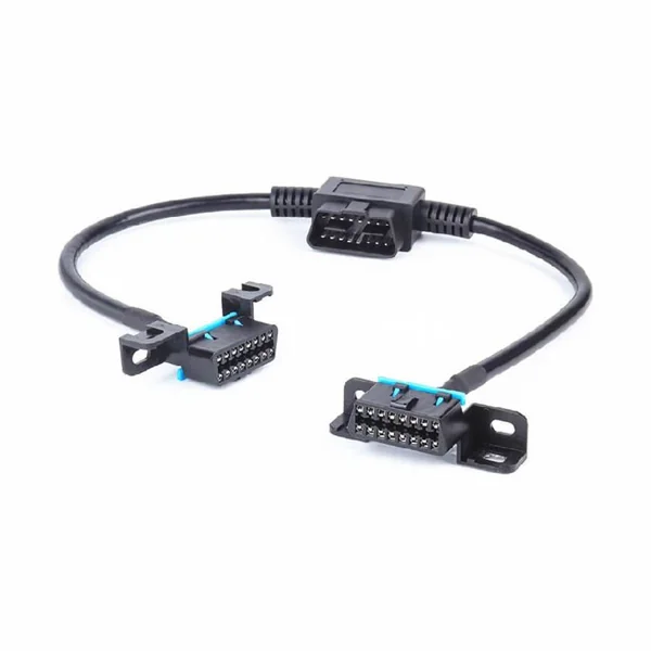
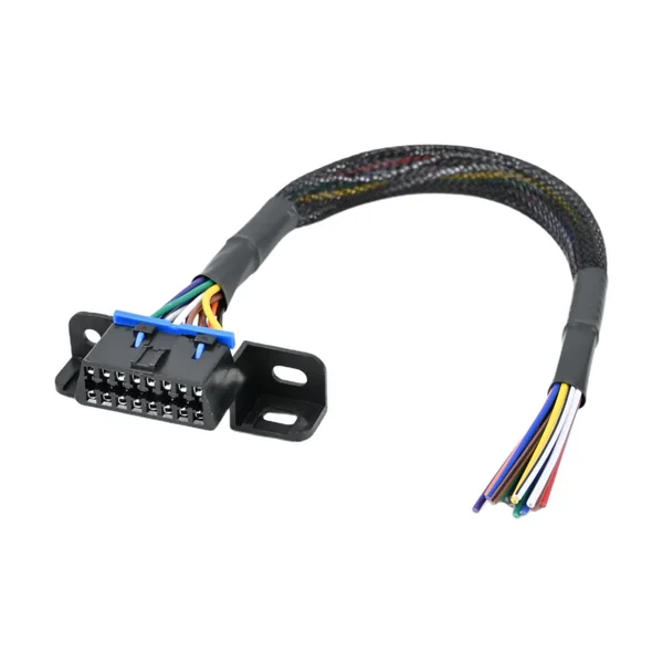
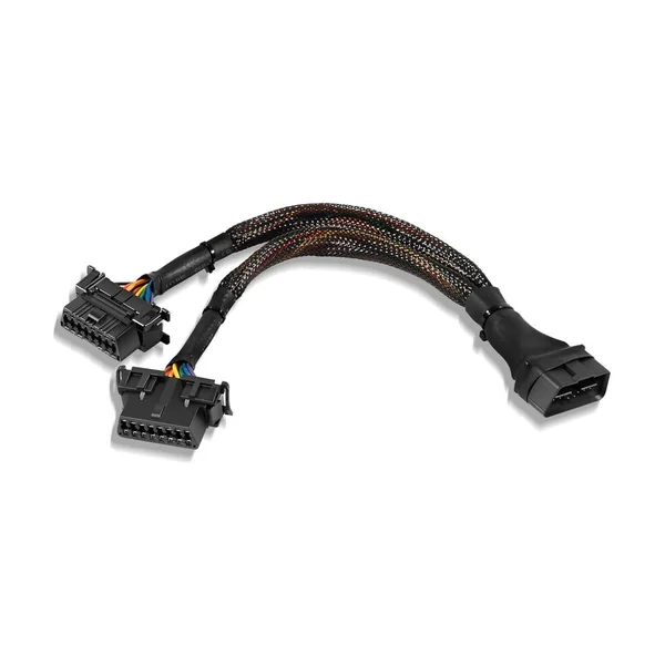
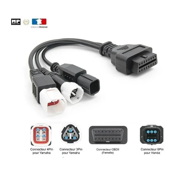
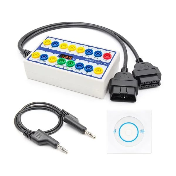
The same category can include straight and right-angle extensions, low-profile flat leads, panel-mount ports, pass-through harnesses, Y splitters, switch-controlled branches, breakout leads, scan-tool adapters, data-logger tails, telematics power-and-data harnesses and legacy-vehicle conversion cables. Each format changes access, strain, branch loading, service sequence and the risk of disturbing another device. Finished drawings should show connector view, orientation, cable exit, length datum, branch point, labels and device-side termination.
Define the use case
Reading emissions data, workshop diagnosis, logging and reprogramming can require different conductors and validation.
Separate light- and heavy-duty
J1962-style OBD leads and J1939 or J1708 truck interfaces are related but not interchangeable categories.
02
STANDARD INTERFACE
J1962 and ISO 15031-3 define a physical diagnostic connection with controlled contacts
The standardized connection comprises a vehicle connector and an external test-equipment connector. Requirements cover connector design, access or location, contact allocation and related electrical circuits. The familiar trapezoidal housing is intended to support standardized access, but housing gender, Type A or Type B details, terminal construction, retention and mating geometry still need exact component identification. The connector is not treated as a generic 16-way plug selected by appearance.
Control the mating face
Pin numbering is verified from the defined mating view, not inferred from the wire-exit side.
Respect short-term access
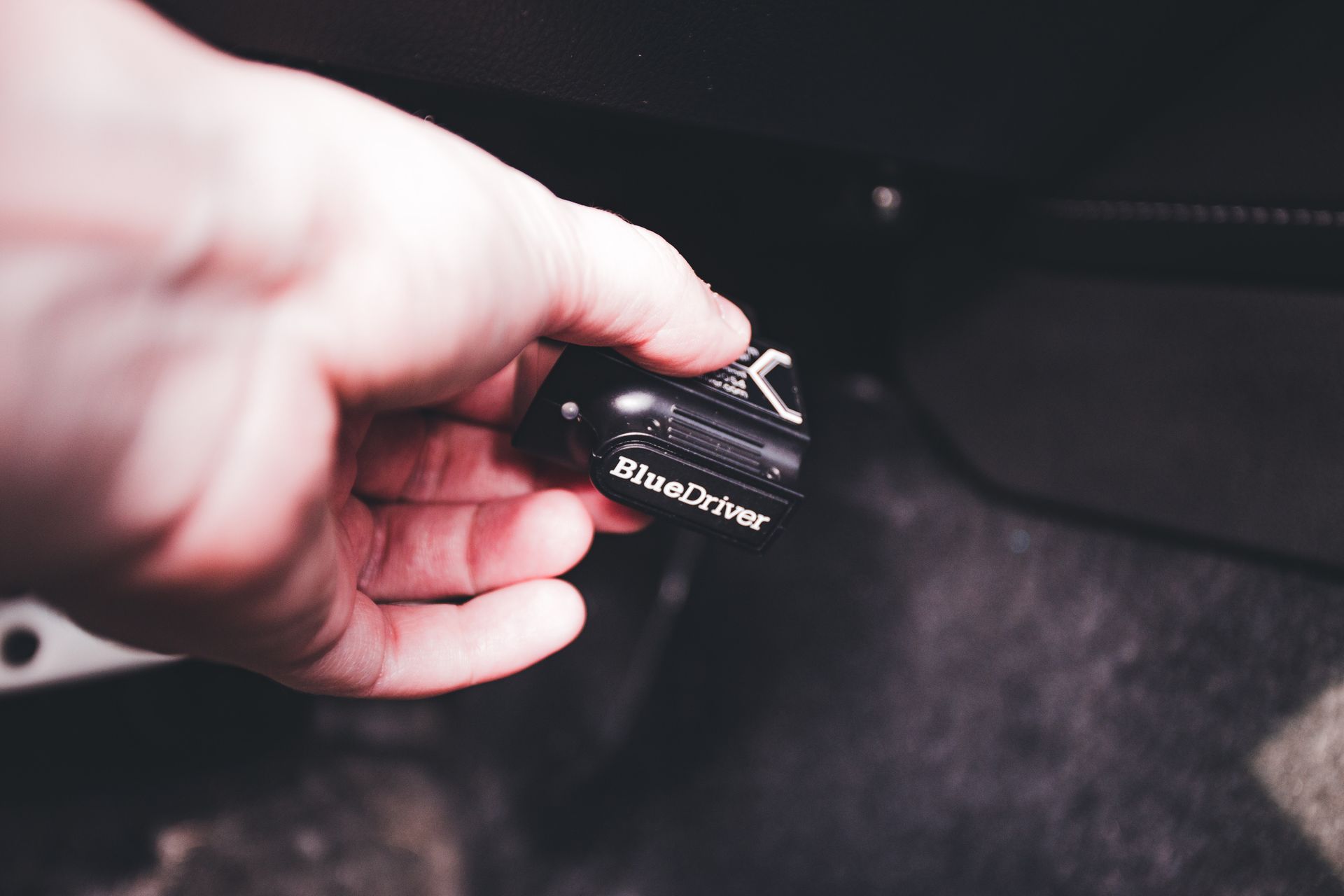
Standard diagnostic access does not by itself authorize a permanent device, splitter or unsupported cable load.
03
PIN MAP
Standardized contacts and manufacturer-discretionary contacts must not be confused
Power, signal grounds and standardized diagnostic buses occupy defined functions in applicable implementations, while other positions may be assigned by the vehicle manufacturer. A fully populated extension can preserve every contact, but an adapter or device lead may intentionally use only a controlled subset. Unused cavities, bridged grounds, swapped CAN polarity, accidental battery feed or copied legacy pinouts can damage tools or prevent communication. Every circuit is released by pin number, function, conductor and destination.
Do not use color as the pin map
Wire color supports assembly and service, but the drawing and electrical test own the circuit definition.
Document intentional omissions
A four-wire CAN lead and a sixteen-core pass-through are different products even with identical shells.
04
PHYSICAL LAYERS
The harness must preserve the electrical behavior required by the active protocol
OBD access may use CAN-based diagnostics or earlier physical layers such as K-line or other regulated and manufacturer-specific arrangements. The harness does not create protocol compatibility: it only transports the released circuits. CAN conductors may require a controlled twisted pair, suitable impedance behavior and limited untwist; single-wire circuits need correct reference grounds; higher-speed diagnostic Ethernet or pass-through applications can impose a different connector and cable architecture. Length, branching, shielding and adapters are reviewed against the actual interface.
Protocol is not connector shape
A tool can mate mechanically and still lack the required transceiver, wiring or software session.
Limit uncontrolled stubs
Long splitter branches and extra devices can alter loading and reflections on a communication bus.
05
POWER & GROUND
Diagnostic-port power is a circuit to engineer, not a free auxiliary outlet
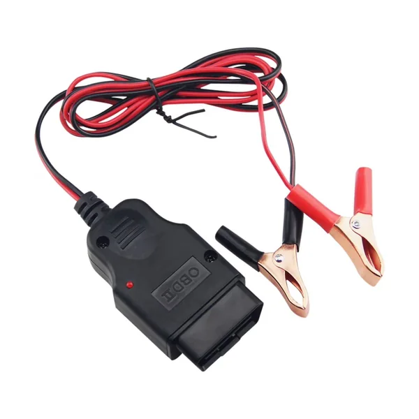
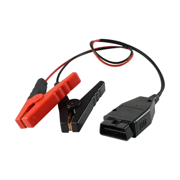
Tools, loggers and telematics devices may draw power from the diagnostic connector, but available current, fuse coordination, sleep behavior, battery drain, inrush, reverse-polarity protection and ground paths depend on the vehicle and device. A splitter can add simultaneous loads that the original use did not anticipate. The harness records conductor area, contact capacity, fuse or protection arrangement, switched or unswitched behavior and whether power is passed through, isolated or provided from an auxiliary source.
Budget continuous and peak load
Wireless modems and test interfaces can have short current peaks above their average consumption.
Keep grounds intentional
Signal and chassis references are not automatically interchangeable or safe to bridge.
06
EXTENSIONS & ROUTING
Low-profile exits and controlled length protect the driver space and connector
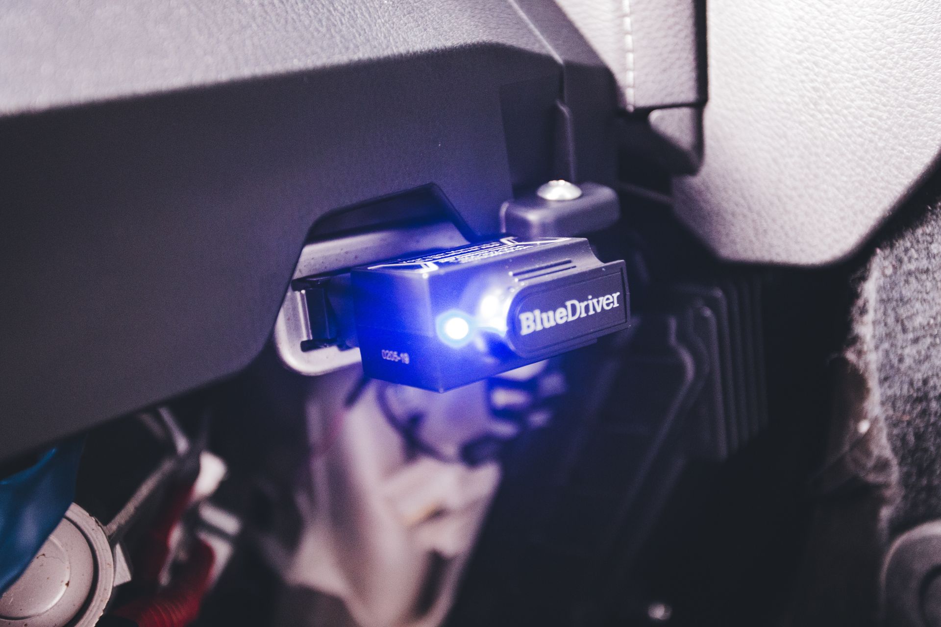
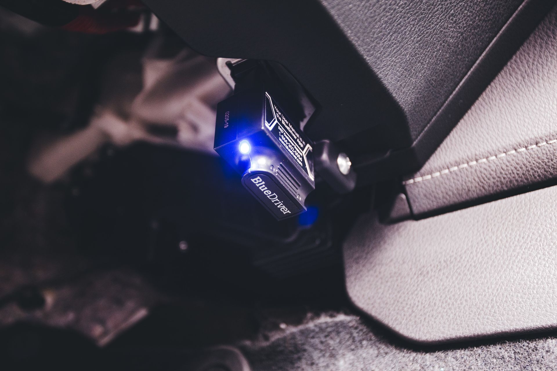
A diagnostic port can sit above the pedals, behind trim, inside a console or close to a knee-impact zone. Straight backshells may be suitable for workshop use but obstruct permanent installations; left-, right-, up- and down-exit overmolds are not interchangeable because vehicle port orientation varies. Cable length, bend radius, clips, abrasion protection, service loop and strain relief are arranged so the assembly does not interfere with controls, trim, airbag zones or technician access.
Photograph the installed orientation
A connector-face photo plus surrounding space prevents a correct plug from receiving the wrong cable exit.
Avoid hanging mass
A VCI, logger or adapter should be supported rather than left loading the vehicle connector.
07
SPLITTERS
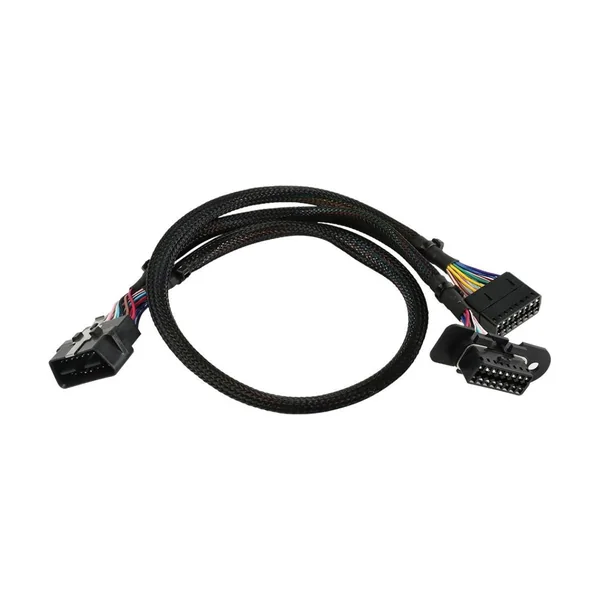
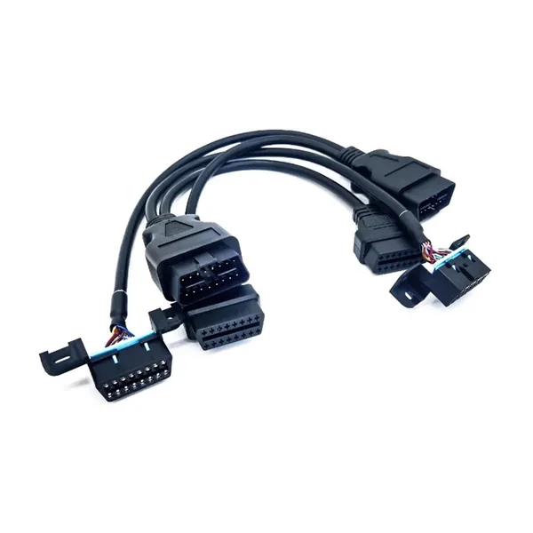
A Y splitter must define which circuits are shared, isolated or switched
A pass-through assembly may keep a service port accessible while a logger or telematics device remains installed. Simply connecting every pin in parallel can create two powered devices, duplicate termination or loading, unintended wake-up traffic, ground interaction and physical crowding. The released architecture identifies the primary and secondary branches, circuit pass-through, power switching or protection, branch length, device priority and acceptable simultaneous operation. When isolation electronics are required, the product becomes more than a passive cable.
Specify passive or active
A passive copper splitter cannot provide protocol arbitration or galvanic isolation by itself.
Preserve service access
Labels and branch geometry should make the removable device and workshop port unmistakable.
08
VEHICLE ADAPTERS
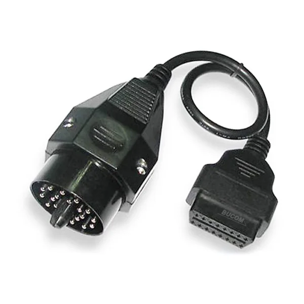
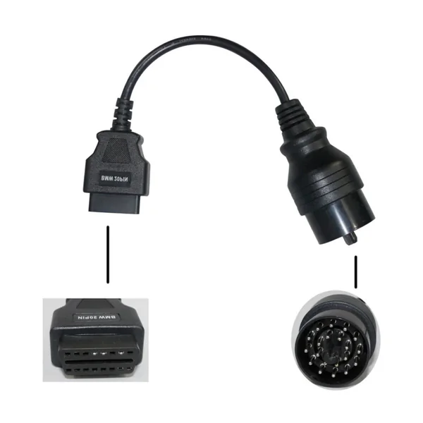
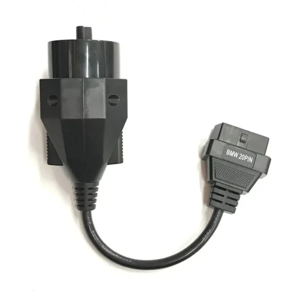
Legacy and manufacturer-specific adapters translate a released pinout, not a brand name
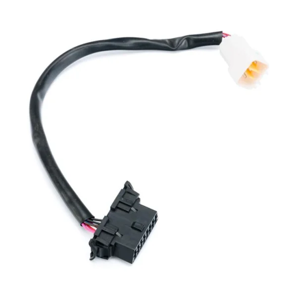
Older vehicles and specialist systems can use round, rectangular or multi-pin service connectors that predate or supplement the standardized diagnostic port. Two vehicles from the same brand may use different interfaces by model, year, engine, market or control system. The adapter is defined from the exact vehicle-side connector, mating key, pin map, protocol and scan-tool expectation. Cross-references are treated as evidence to verify, not permission to copy an online pinout without confirmation.
Match exact generation
Model year alone may not identify a mid-cycle connector or ECU change.
Verify both ends
Vehicle-side correctness does not prove the scan-tool-side DB, USB or proprietary interface pinout.
09
DEVICE SIDE
DB, RJ45, USB and proprietary housings do not guarantee a standard diagnostic pinout
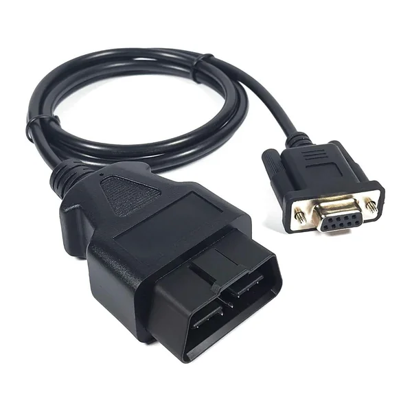
Diagnostic tools often use familiar connector families as convenient hardware while assigning contacts specifically to their own interface. A DB9 may carry CAN, serial signals, power or a proprietary combination; an RJ45-shaped jack need not be Ethernet; a USB-ended product may contain an active interface rather than direct copper wiring. We require the device model, connector identity and approved electrical schedule, then distinguish passive adapters from assemblies containing VCI, level-shifting, protection or conversion electronics.
Name the tool, not only the plug
Tool model, hardware revision and target software ecosystem can affect the required cable.
Declare active electronics
Programming and diagnostic claims cannot be assigned to a passive harness unless the required interface exists elsewhere.
10
CABLE CONSTRUCTION
Conductor groups, twist, shield and jacket follow the signal and installation duty
A compact workshop lead, a permanently routed telematics harness and a long breakout cable do not need identical construction. Conductor area follows signal or power duty; CAN or other balanced pairs may need controlled twist; drain and shield termination follow the interface design; filler, binder and jacket influence roundness and flexibility; abrasion, oil, temperature, flame behavior and low-temperature bending depend on the vehicle zone. Cable markings and material claims are preserved in the bill of materials rather than inferred from color or feel.
Keep pair geometry through termination
Excess untwist and long exposed conductors can weaken the intended noise performance.
Separate cabin and harsh-zone needs
A dry dashboard extension and an under-hood service lead face different heat, fluid and abrasion exposure.
11
MECHANICAL DESIGN
Overmold, backshell and strain relief must protect the cable without blocking vehicle access
Injection overmolding can integrate the connector exit, pull relief, bend transition, tactile orientation and branding, while serviceable backshells support low-volume or configurable assemblies. Polymer choice, pre-mold support, adhesion, terminal retention, cable jacket compatibility and molding pressure are reviewed together. A large attractive mold can still be wrong if it collides with trim, prevents an adjacent port from being used or concentrates bending at the cable edge.
Prototype the envelope
A printed or soft-tool sample can confirm hand clearance and exit direction before hard tooling.
Do not hide poor termination
Crimp, solder or splice quality is accepted before it becomes inaccessible inside molding.
12
MANUFACTURING
Controlled views, tooling and first articles make complex pin maps repeatable
Production documents show the mating-face view, cavity number, circuit name, wire specification, strip length, terminal, seal, crimp tooling, splice, shield termination, backshell or mold and finished dimensions. Work proceeds through material identity checks, cut and strip, terminal setup, insertion, secondary lock, pair and shield preparation, branch assembly, molding where required, labeling and electrical test. First-article review confirms orientation and functional intent before the configuration is released for repeat production.
Use mating-view fixtures
Keyed fixtures reduce mirror-image errors between front and wire-entry views.
Freeze approved alternatives
Connector, terminal, cable and mold changes are reviewed rather than silently substituted.
13
INSPECTION & VALIDATION
Continuity, network communication and reprogramming suitability are different acceptance levels
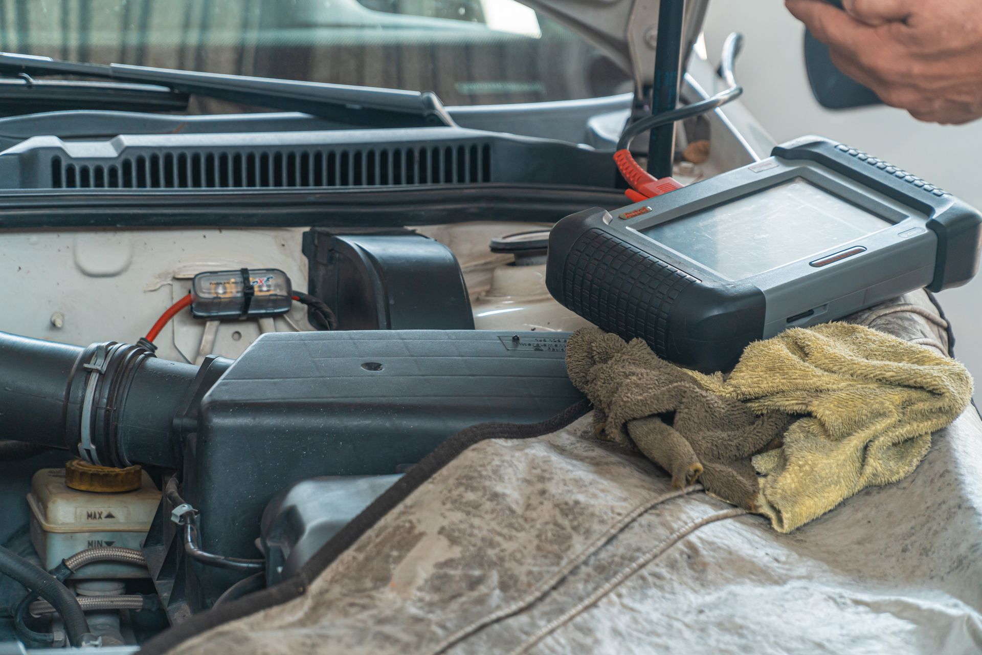
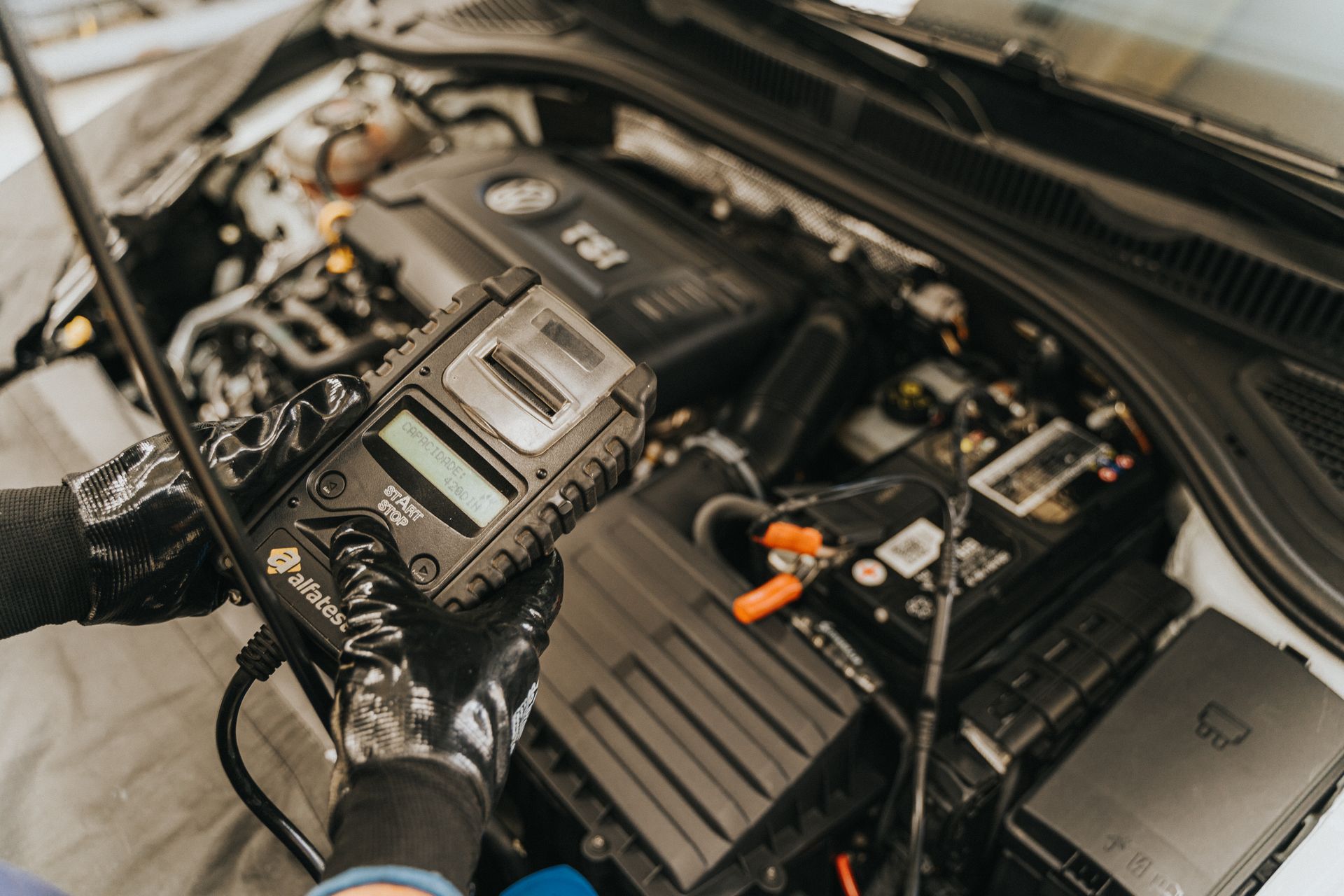
Routine inspection can verify material, connector lock, dimensions, labels, pin-to-pin continuity, shorts and visual workmanship. Resistance, shield checks, insulation tests, flex or pull checks are added with defined limits and methods. Communication validation requires the specified vehicle, simulator, VCI or tool and an agreed session; programming adds power stability, software and recovery risks beyond a passive cable check. We report only the level actually tested and do not turn a continuity result into a universal compatibility claim.
Record the tested configuration
Vehicle, tool, software, power source, harness revision and test function keep the evidence interpretable.
Retain traceability
Material lot, crimp setup, operator checks and final test remain linked to the delivered batch.
Automotive Diagnostic & OBD Harness Questions
Does every 16-pin OBD connector have the same wiring?
No. The standardized connector defines controlled functions and leaves some contacts for manufacturer discretion. Vehicle generation, market, protocol and target task still determine the released pin map.
Can you make a full 16-core male-to-female extension?
Yes, after confirming connector type, orientation, all pin-to-pin circuits, conductor sizes, length, exit direction and intended use. A fully populated extension can also pass manufacturer-specific circuits, so the application still matters.
Will an OBD-to-DB9 or OBD-to-RJ45 cable work with any tool?
No. DB9 and RJ45 describe connector families, not a universal diagnostic contact assignment. The exact tool model and approved device-side pinout are required.
Can two devices share the diagnostic port through a Y splitter?
Only after power load, bus loading, wake-up behavior, grounds, branch length, device priority and simultaneous-operation rules are reviewed. Passive parallel wiring is not automatically safe or compatible.
Can a passive OBD harness perform ECU programming?
A passive harness only connects released circuits. Programming additionally depends on the correct VCI or pass-through hardware, protocol support, software, vehicle access, stable power and an approved procedure.
What should be sent for a custom OBD harness review?
Send vehicle make, model, year and market; the target task; photos of the installed port; exact tool or device; connector part numbers or samples; approved pin maps and protocol; power load; cable length and exit; branch behavior; environment; quantity; labels; and required tests.
SAE J1962 and ISO 15031-3 define requirements for the standardized diagnostic connection between the vehicle and external test equipment, including connector design, contact allocation and related electrical circuits. The standardized shell can carry different physical layers and manufacturer-discretionary circuits.
02 Project Inputs
Provide vehicle make, model, year and market; target diagnostic or data task; vehicle-side connector and access space; exact device or tool interface; released pin map and protocol; power source and current; cable length and exit direction; shielding and termination requirements; whether another device must remain connected; environmental exposure; quantity; labels; and required inspection or functional checks.
03 Release Records
We can develop from a controlled drawing, verified sample, connector part numbers or an approved interface schedule. Before sampling, the vehicle-side and device-side identities, power routing, signal conductors, grounds, shields, branch behavior and mechanical envelope are frozen. Continuity proves wiring correspondence only;
04 Interface Review
Confirm the exact mating interface, pin map, dimensions and installation orientation.
05 Sample Acceptance
Agree the sample configuration and electrical, mechanical or environmental checks required by the project.
06 Change Control
Record changes to materials, drawings and process instructions before repeat manufacture.
Send the part number, drawing or sample to confirm the replacement configuration and sourcing plan.
PROJECT REVIEW / CUSTOM MANUFACTURING
Custom Wire Harness Manufacturing in China
Custom wire harness manufacturing from our China factory, with OEM/ODM project support.
A sample, clear connector photos or a description of the equipment and required quantity is enough to start a review.