

Construction Vehicle Harness
OverviewConstruction vehicle harnesses distribute power, control, sensor and communication circuits across off-road machines and their attachments.
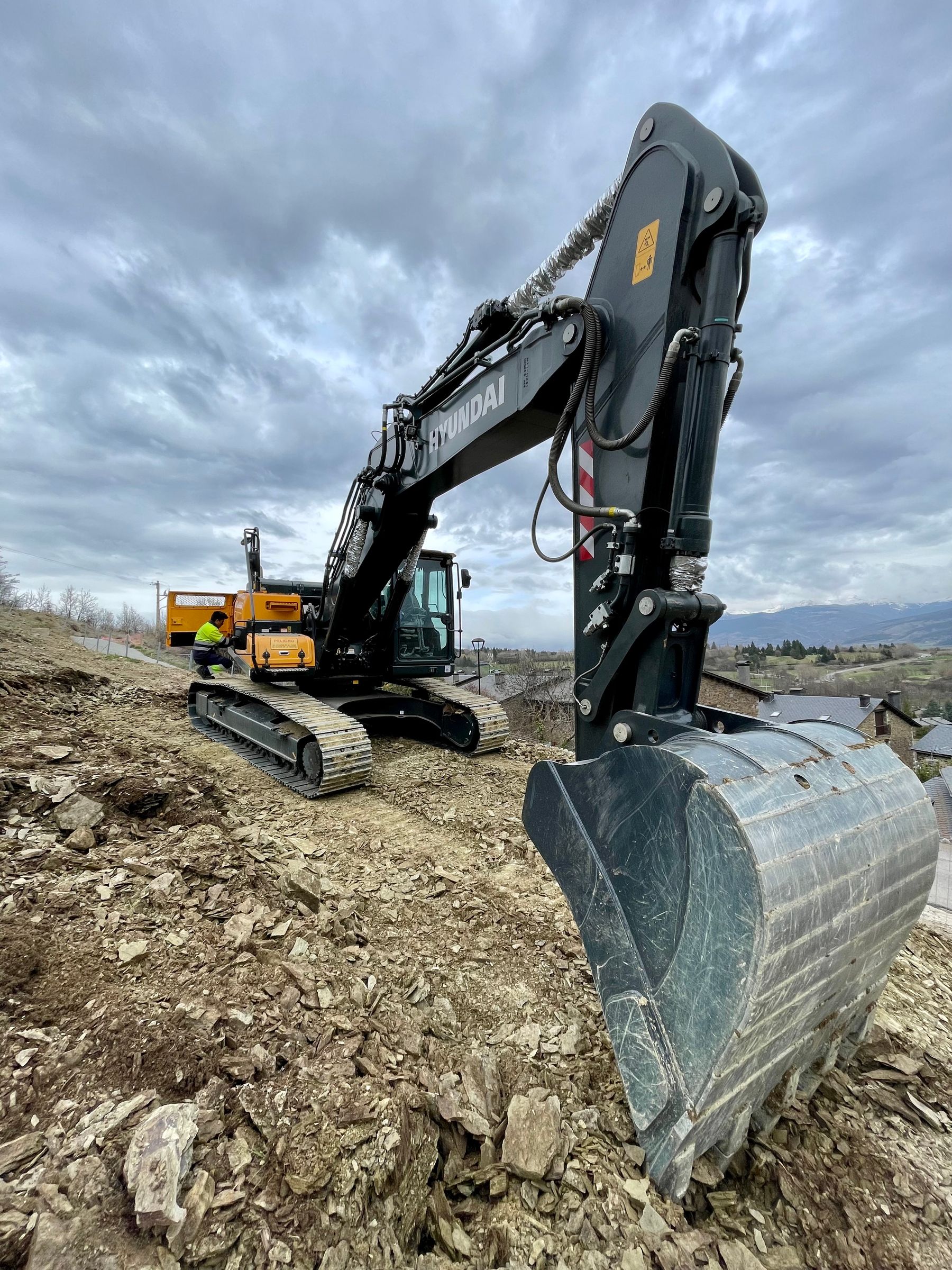
Popular Product Photos
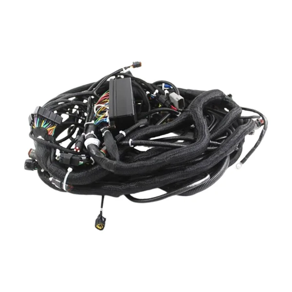
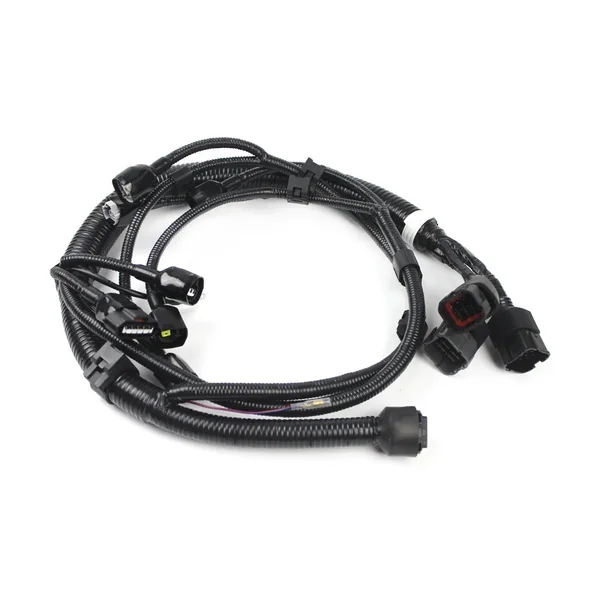
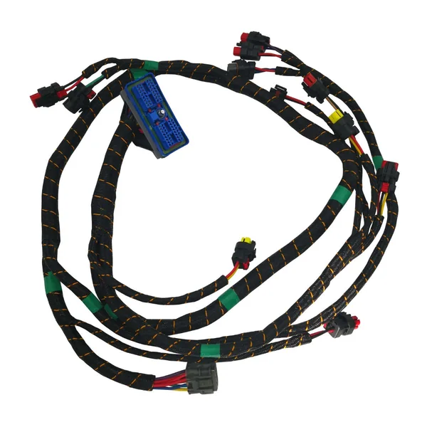
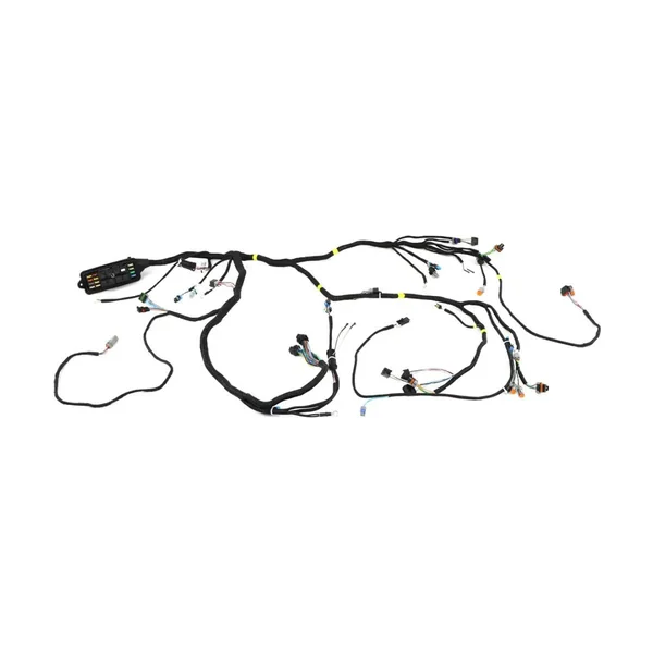
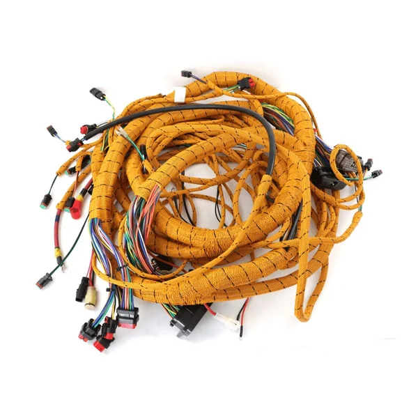
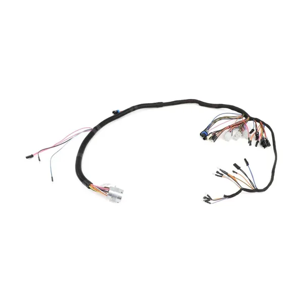
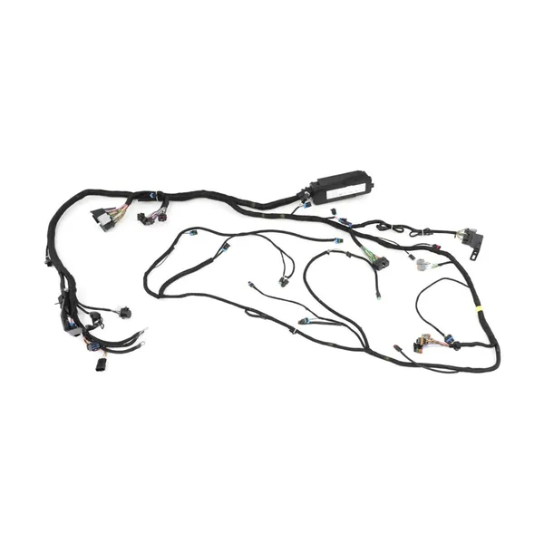
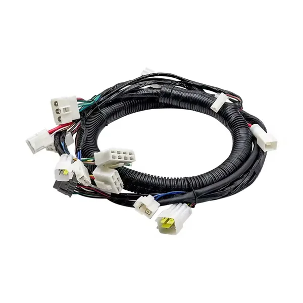
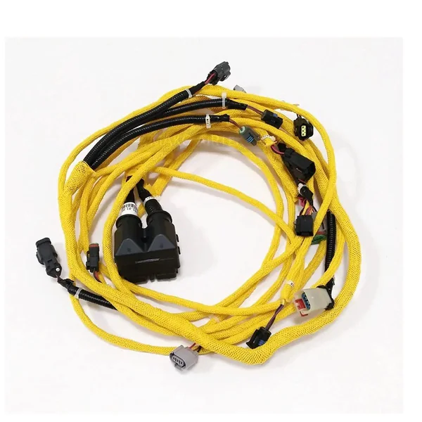
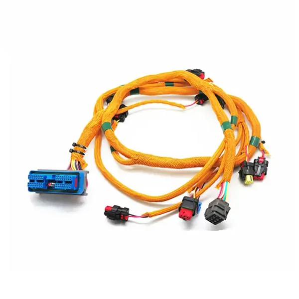
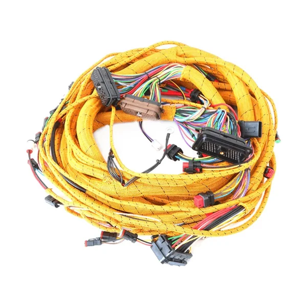
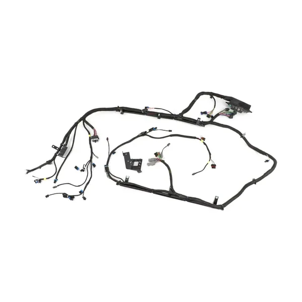
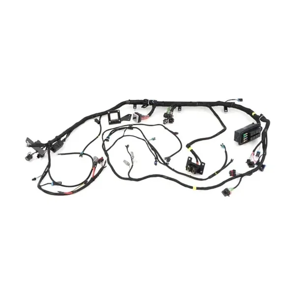
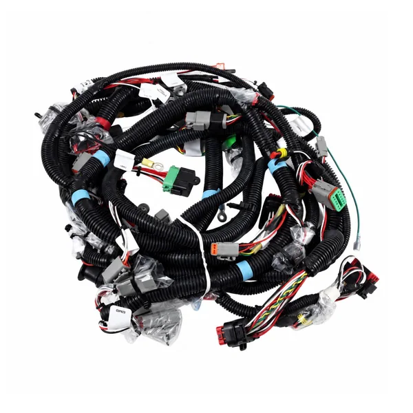
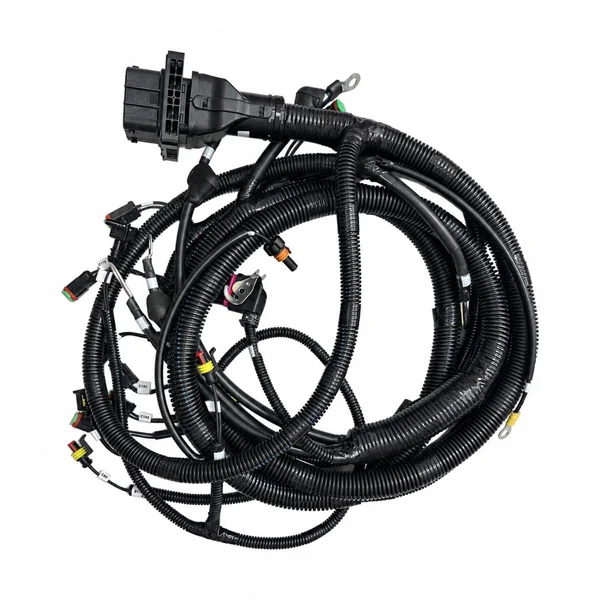
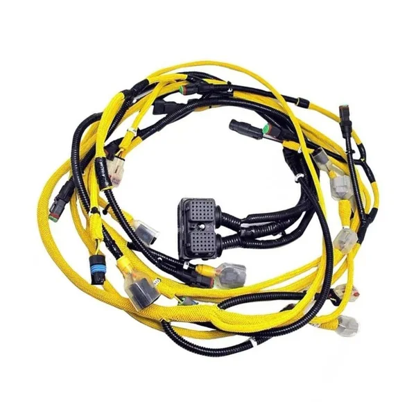
PART NUMBER / INTERFACE / MATERIAL
Models, Part Numbers & Sourcing
Find a cable model or material part number, then send it for a custom replacement or original-part sourcing review.
No matching references. Try a brand, full part number or a listed alias.
Cable & Harness Models
Manufacturer-identified finished assemblies for this application.
- PEAK-System
IPEK-003009
PCAN-Cable J1939, Type 1 DEUTSCH to D-Sub
Custom compatible replacements · Original-parts sourcing
- PEAK-System
IPEK-003019
PCAN-Cable J1939, Type 2 DEUTSCH to D-Sub
Custom compatible replacements · Original-parts sourcing
- PEAK-System
IPEK-003014
PCAN-Cable J1939, Type 1 DEUTSCH to 2 x D-Sub
Custom compatible replacements · Original-parts sourcing
- PEAK-System
IPEK-003015
PCAN-Cable J1939, Type 2 DEUTSCH to 2 x D-Sub
Custom compatible replacements · Original-parts sourcing
- Caterpillar
350-8108
Chassis Wiring Harness for Excavator
Custom compatible replacements · Original-parts sourcing
Selection & Project Review
01 Application Boundary
Off-road machines combine mobile-vehicle wiring with industrial actuators, hydraulic systems and exposed articulation. Harness design must follow the actual machine zone, movement envelope, duty cycle and service method. Connector sealing alone cannot compensate for poor routing, unsupported mass, trapped water, excessive branch stiffness or the wrong terminal and wire-seal combination.
02 Project Inputs
Provide machine maker, model and serial range; equipment type and installed attachments; voltage architecture; controller, valve, sensor and actuator data; drawings, samples and mating interfaces; circuit and network definitions; boom, articulation and service movement; heat, dust, mud, washdown, oil and chemical zones; clips, brackets and pass-throughs; branch datums; labels; quantity; and validation requirements.
03 Release Records
Approved requirements are converted into controlled drawings, circuit lists, BOMs, splice maps, form-board datums, protection instructions, labels and test programs. First articles are checked on the target machine or representative fixture for reach, movement, clearance, connector access and agreed function before repeat production. Evidence is released by machine configuration and drawing revision.
04 Interface Review
Confirm the exact mating interface, pin map, dimensions and installation orientation.
05 Sample Acceptance
Agree the sample configuration and electrical, mechanical or environmental checks required by the project.
06 Change Control
Record changes to materials, drawings and process instructions before repeat manufacture.
Send the part number, drawing or sample to confirm the replacement configuration and sourcing plan.