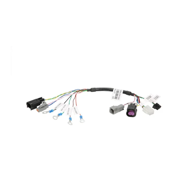
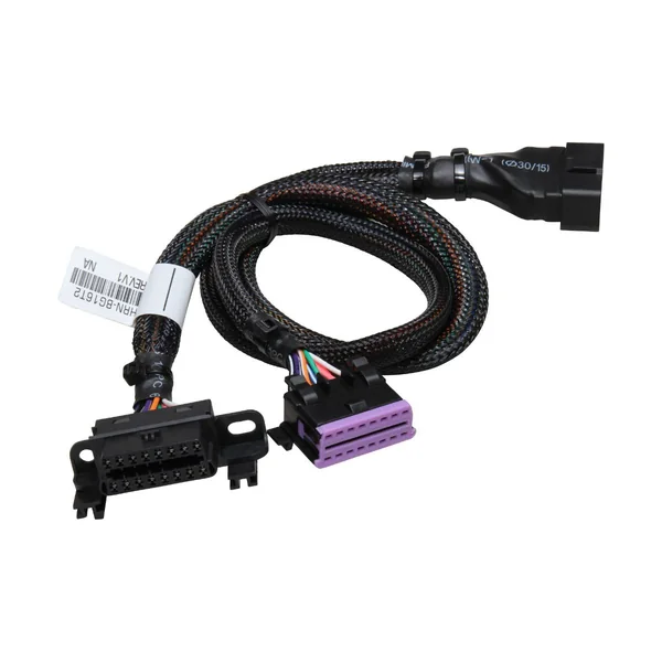
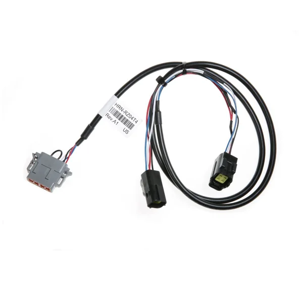
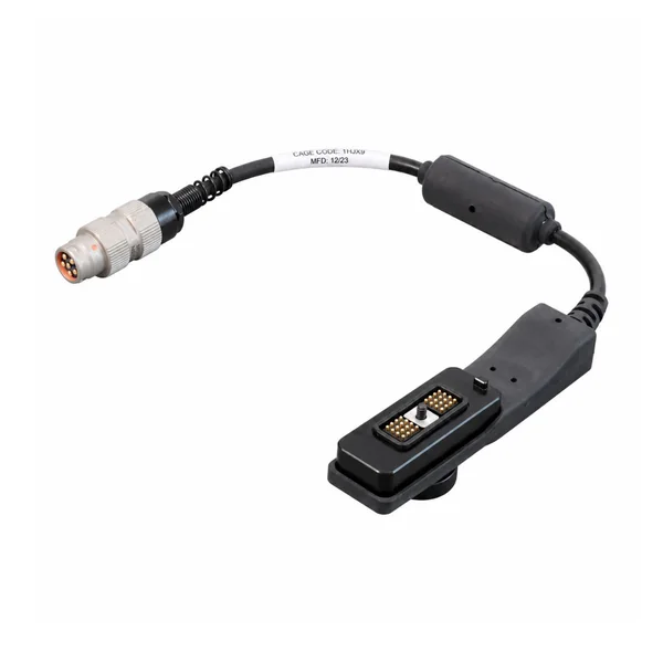
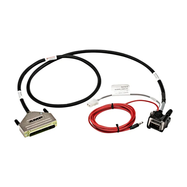
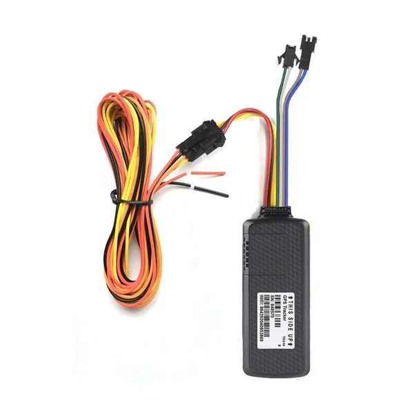
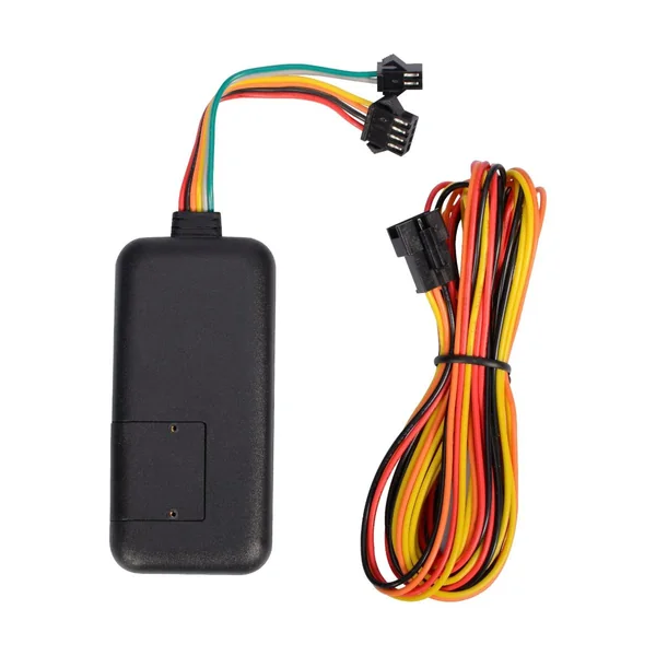
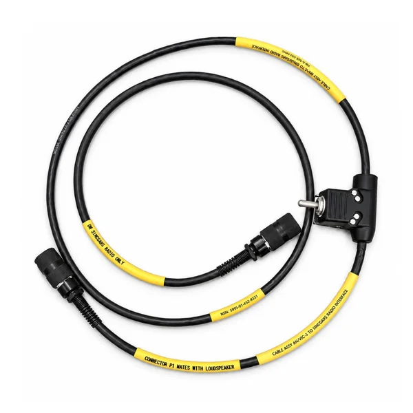
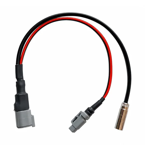
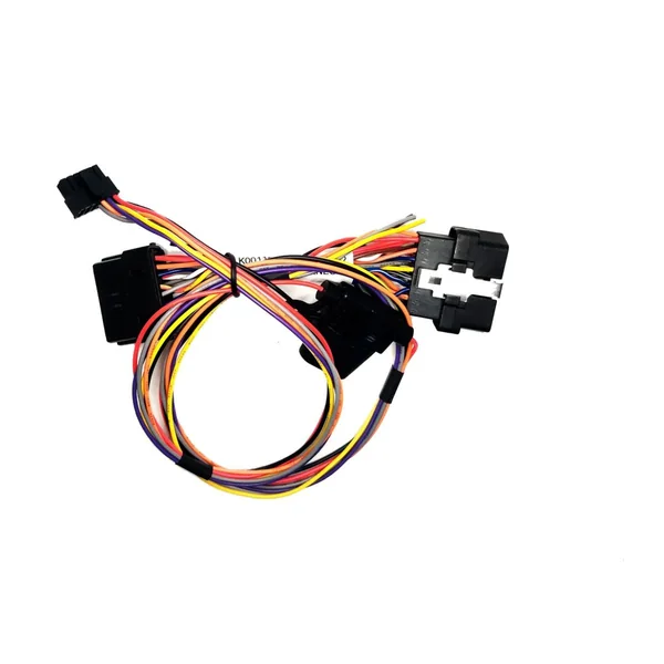
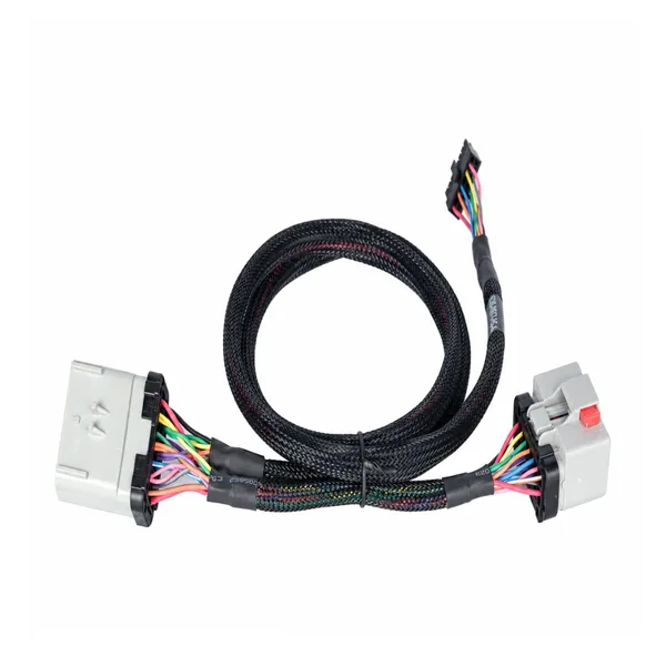
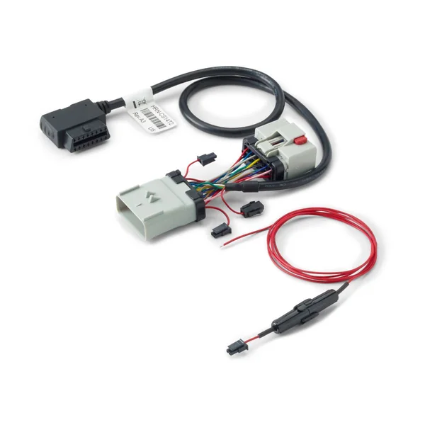
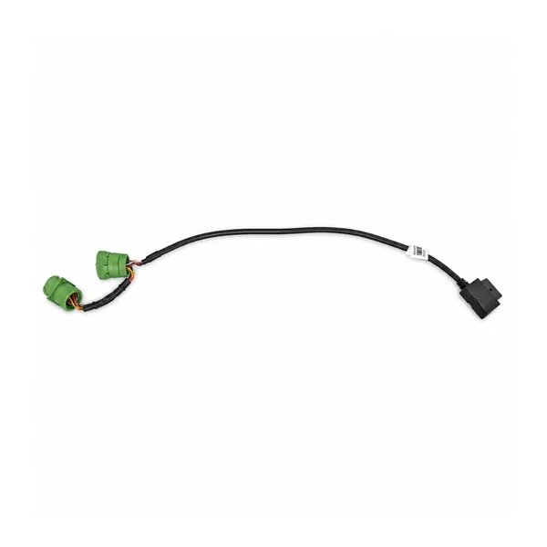
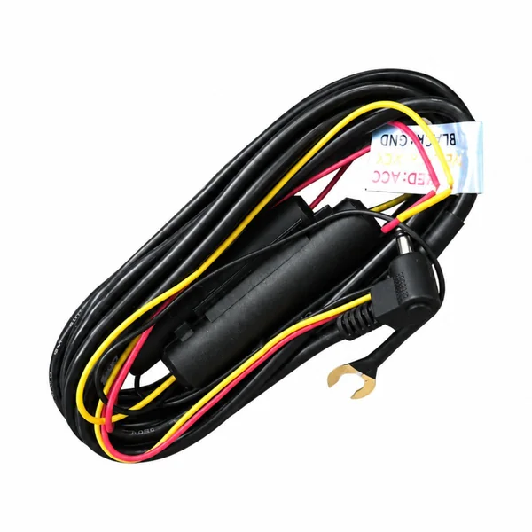
Custom GNSS antenna leads, tracker power looms and vehicle-specific communication adapters, coordinated around the receiver, vehicle interface and installation.
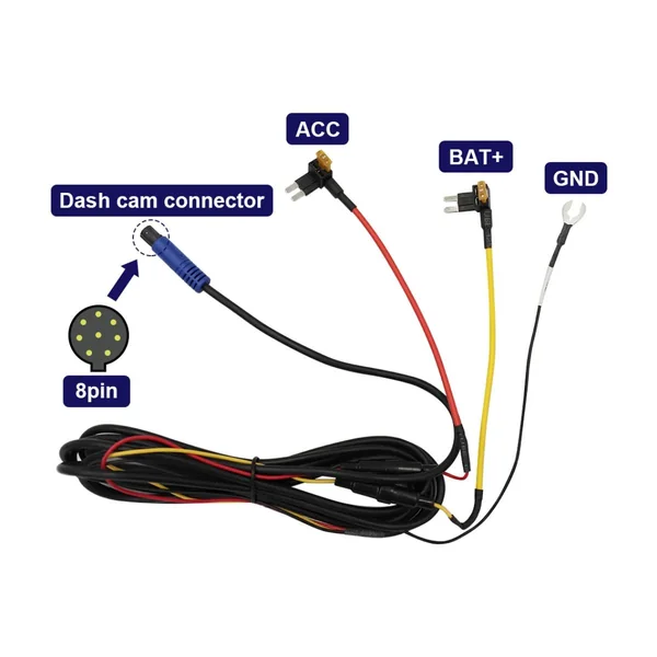
Dash Camera Circular Main Plug & Spade-Terminal Harness
Product Introduction
A GPS harness is not one universal cable. A navigation receiver may need a coaxial antenna extension; a fleet tracker may need a fused supply, ignition input and separate sensor leads; a telematics gateway may require a vehicle-specific data adapter. GNSS includes GPS and other satellite constellations, while cellular communication carries reports to a server. These functions use different interfaces. Super Smile develops the connecting assembly from drawings, samples and equipment documentation. The tracker, antenna electronics, software subscription and vehicle permissions remain distinct parts of the system unless separately included in the project scope.
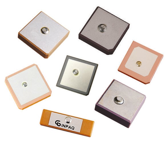
Ceramic patch antennas illustrate GNSS receiving elements; the receiver and harness are separate components.An external GNSS antenna uses a dedicated coax lead; cable length is part of its RF budget.
01
Product Advantages: Vehicle Antenna Extensions
An extension allows the antenna and receiver to occupy different locations without forcing the electronics into the antenna's best reception position. Its value depends on the entire RF path. Additional length and adapters introduce loss; a longer lead does not amplify a satellite signal. Define connector series, keying, cable type, route and the required frequency range before quoting. FAKRA, SMA, SMB and compact board-side coax interfaces are examples, not interchangeable choices. A controlled assembly keeps the bend and strain away from the contact, preserves the intended impedance and provides enough access for installation without an unnecessary coil of spare cable.
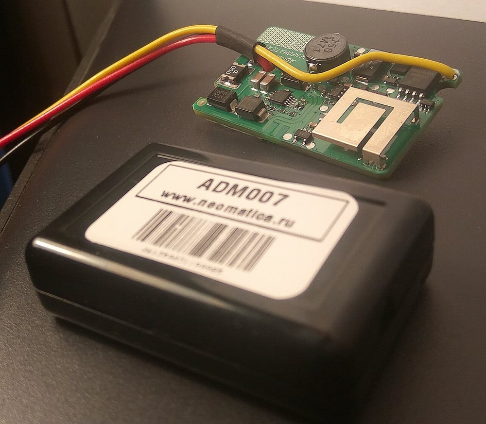
An opened tracker illustrates the relationship between enclosure, module and connecting wires.
02
Wired GPS Trackers and Compact Units
A wired tracker can combine a GNSS receiver, cellular modem, accelerometer and backup battery, but the harness only connects the functions supported by the selected unit. Some devices use internal antennas and need no external RF lead. Others expose separate GNSS and cellular sockets that must not be swapped. Record the device revision, supply range, connector pinout and any analog or digital inputs. Teltonika FMC920 is one example of a compact tracker architecture, not a universal pin assignment. For an installation kit, identify what is supplied as cable hardware and what remains the integrator's responsibility: configuration, SIM service, mounting, consent and account access.
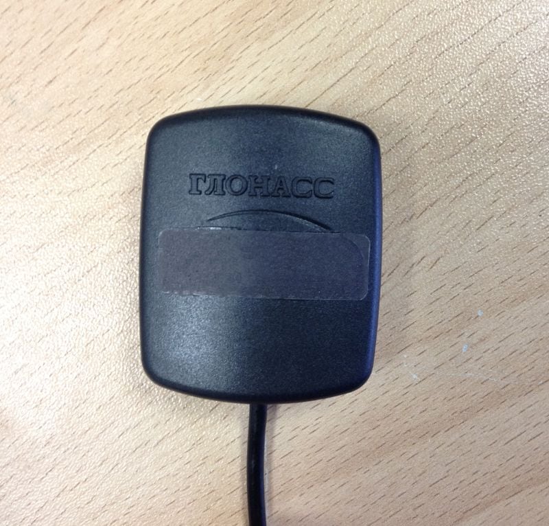
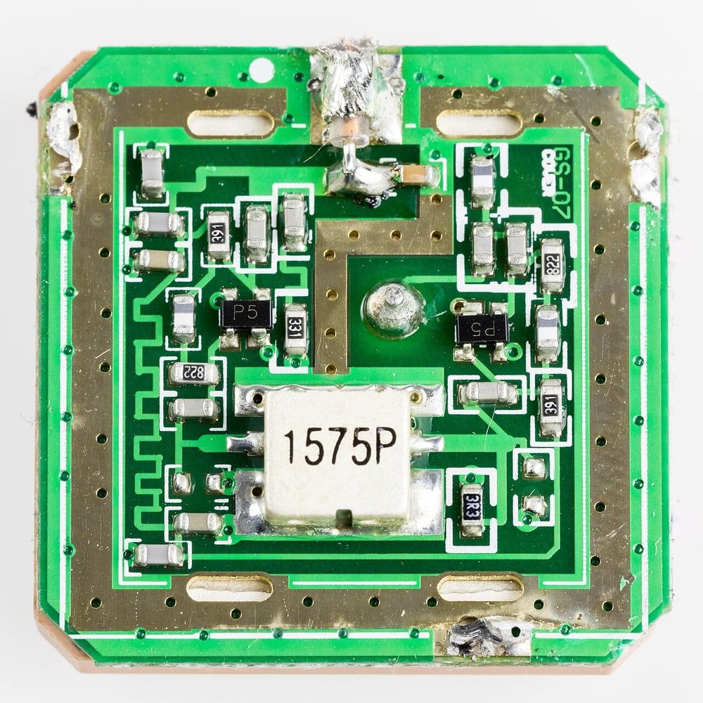
An active GPS antenna exposes its electronics beneath the cover.
03
The External GPS / GNSS Antenna
Antenna placement is an RF decision as well as a mounting decision. Nearby metal, coated glazing, the ground plane and the enclosure can alter reception. An active antenna contains amplification and requires a compatible bias supply, often carried on the coax; a passive antenna has different needs. Confirm supported bands, bias voltage and current, connector and cable loss against the receiver documentation. A roof-mounted antenna may improve its view of the sky, but the cable entry still needs sealing and strain control. Cable quality cannot remove satellite blockage in a tunnel or guarantee a position fix between tall buildings.
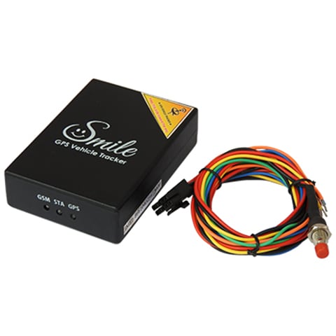
A third-party tracker and cable set illustrates a device-side branch; it is not a universal vehicle T-harness.
04
Solution: Vehicle-Specific T-Harness / Adapter
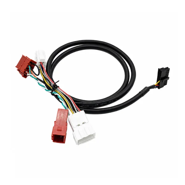
A T-harness introduces an approved branch between a known pair of mating vehicle interfaces. The drawing must preserve every pass-through circuit and identify the new branch, including which pins are intentionally unused. Similar housings can carry different functions across model years and equipment packages. Document the original connector reference, terminal system, cavity numbering and latch orientation; photographs alone may not establish the circuit. Avoid arbitrary connections to safety-critical controllers. Vehicle data access may require an approved gateway, software support or permissions. The harness provides physical interconnection; it does not grant access to protected data or translate protocols by itself.
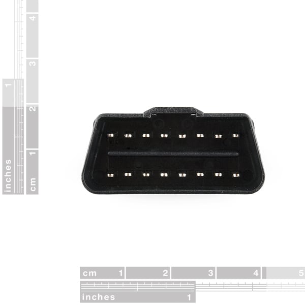
A diagnostic plug illustrates cavity layout; a wiring drawing defines the actual pass-through circuits.
05
OBD II Extension Cable / Splitter
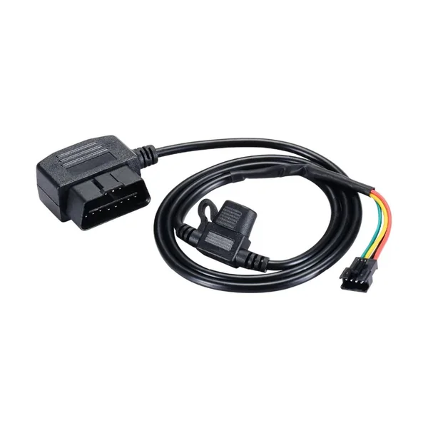
An OBD extension can move a telematics device away from the driver's knee space while preserving service access. A splitter needs more review than simply duplicating the connector. Connected devices can affect bus loading, diagnostic sessions and vehicle sleep behavior. The familiar 16-position diagnostic interface does not mean every cavity has the same use on every vehicle, nor that an adapter contains a fuse or protocol converter. Specify pass-through pins, branch lengths, current demand, the service-tool use case and any CAN topology limits. Validate the complete installation on the intended platform; a mechanical fit is not evidence that two diagnostic devices can communicate simultaneously.
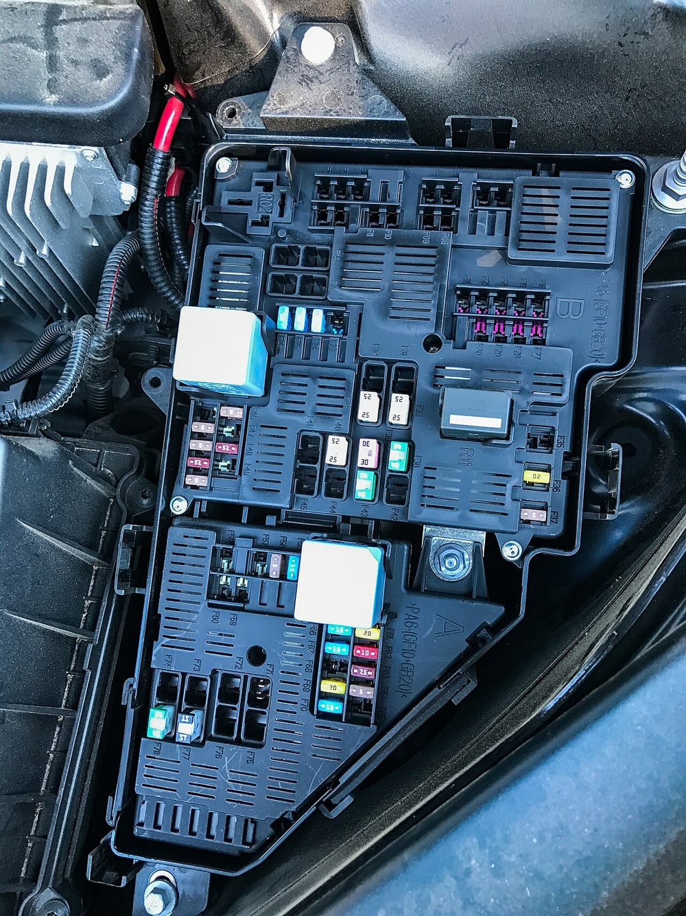
An automotive fuse box illustrates the environment around protected vehicle feeds.
06
Tracker Power Harness with Fuse
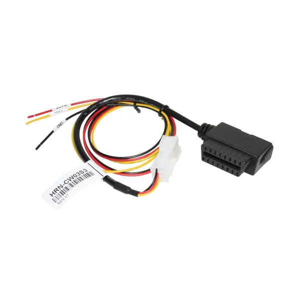
Power, ground and ignition sensing are separate circuit functions. A permanent supply can keep a tracker alive when the vehicle is parked, but standby consumption and the vehicle's sleep strategy must be considered. An ACC feed is not automatically the required ignition signal. Select conductor size, fuse characteristics and the connection point from the device load and the vehicle-approved installation, not from a universal color rule. Put protection where it can protect the intended branch and remain serviceable. Confirm the ground reference and operation during cranking. A passive power loom does not regulate a supply outside the device's allowable range.
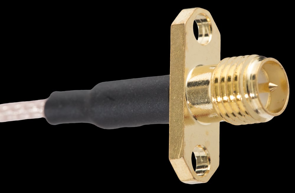
An RP-SMA coax termination illustrates cable-to-contact construction; RP-SMA and SMA mating polarity must be distinguished.
07
Material Recommendation: Copper and RF Coaxial Cable
Power conductors are selected for resistance, voltage drop, flexibility and termination. Tinning can support corrosion resistance and certain joining processes, but it does not make the complete assembly waterproof. The antenna path instead needs a specified coaxial construction: center conductor, dielectric, shield and jacket work together. Common GNSS interfaces use a nominal 50-ohm path; verify the selected receiver rather than substituting a 75-ohm video cable because it looks similar. RG174 and RG316 are familiar reference cable types, with different construction and loss characteristics. Length, bend limits, contact preparation and the mating connector must be specified as a combination.
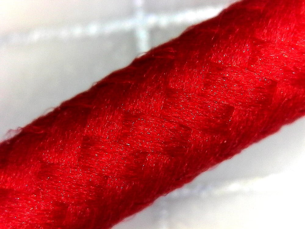
A textile-braided cable close-up illustrates external abrasion protection, not conductive shielding.
08
Braided Sheath, Polymer Jacket and Shielding Mesh
Textile sleeving and conductive braid have different roles. A textile sheath helps manage abrasion and bundling; a metallic screen controls an electromagnetic boundary when properly terminated. Neither can compensate for a damaged coax dielectric. Specify jacket material from temperature, oils, sunlight, flexibility and mounting conditions. An overmold may provide strain relief or environmental protection, but molding resin, adhesion, connector geometry and validation determine the result. Drainage and a controlled drip path can matter as much as an external cover. Avoid labeling every braided or molded assembly waterproof without defining the mated condition and test method.
Delivery vehicles illustrate repeated fleet installations across several units.
09
Industries and Applications: Fleet Management & Logistics
Delivery vans, buses and heavy trucks can share a telematics platform while needing different harnesses. Supply architecture, connector locations and available data interfaces vary between vehicles. A repeatable kit defines branch labels, mounting references and the permitted connection method, reducing ambiguity during fleet installation. Navigation reception, cellular coverage and vehicle data availability should be evaluated separately. The cable assembly cannot guarantee real-time reporting when the network is unavailable. Fleet operators also need an authorized process for driver information, access control and retention of tracking data; these are operational responsibilities outside the physical wiring specification.
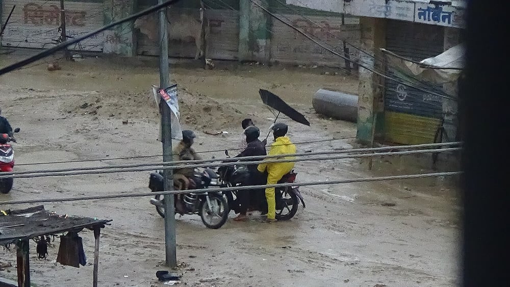
Rain and road exposure illustrate the environmental review needed for open vehicle installations.
10
Motorcycles, Heavy Equipment and Outdoor Installations
Small vehicles need flexible routes around steering and suspension movement; construction equipment adds dust, vibration and frequent servicing. Marine or exposed installations introduce salt, UV and water-entry concerns that require a separate specification. Choose the connector's sealed version where needed, define strain relief and keep harnesses clear of moving and hot parts. A short assembly still needs a minimum bend radius and secure support. Antenna location must preserve both reception and physical protection. These projects can share manufacturing methods with fleet harnesses, but their environmental acceptance criteria cannot be assumed from a sheltered passenger-car installation.
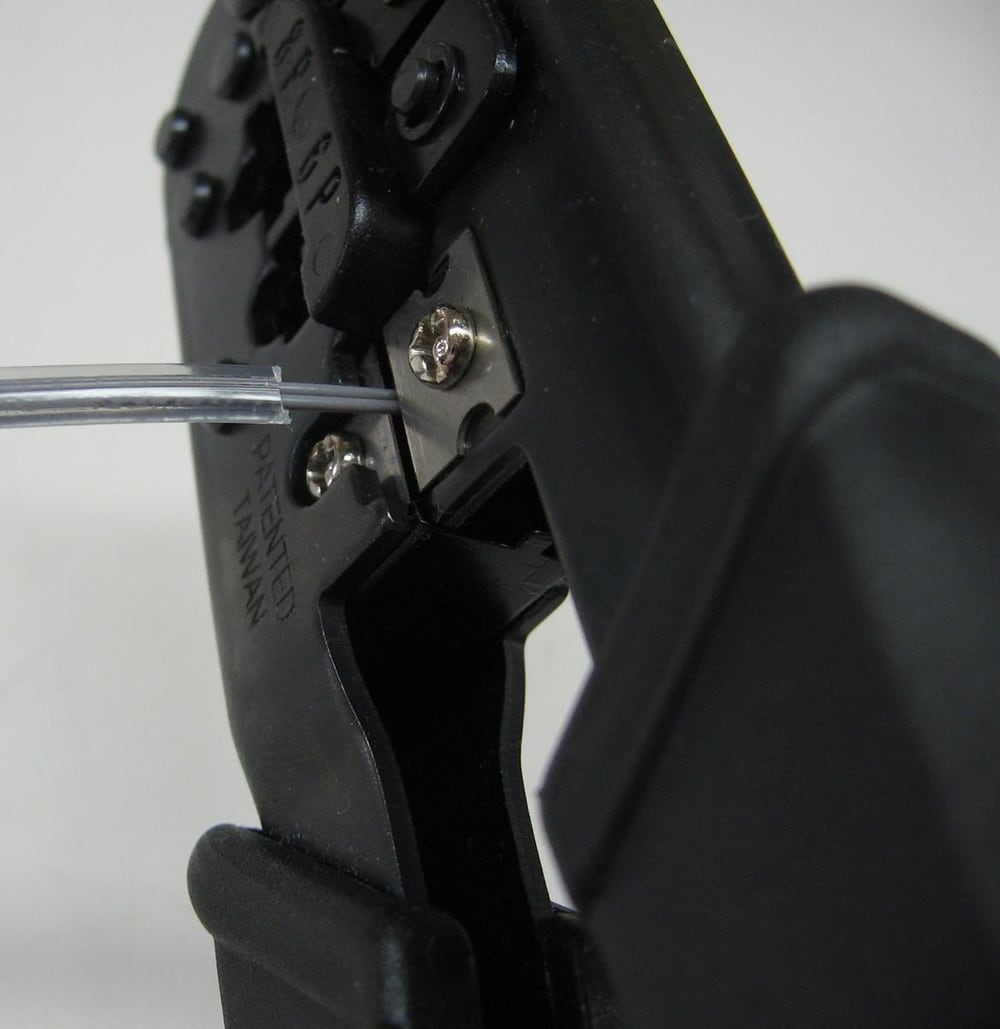
Controlled wire stripping is one preparation step before the specified termination process.
11
Advanced Manufacturing & Customization
The process begins with a controlled pin map and routing drawing, followed by connector and cable confirmation. Power branches are cut, stripped and terminated with the specified tooling. Coax preparation separately controls the exposed center conductor, dielectric and shield lengths so stray strands cannot bridge the contact. Labels distinguish GNSS, cellular, power and data connections before installation. Prototype review checks mating, latch access, routing and the equipment's operation. Once accepted, the drawing, bill of materials and inspection plan define repeat production. Quantity and lead time depend on component availability and the agreed verification scope rather than a fixed promise for every configuration.
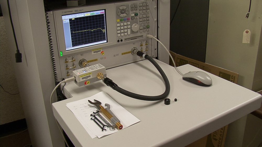
NIST network-analyzer work illustrates RF measurement equipment, not a test of our product.
12
Reliability, Integration and Serviceability
Continuity and pin mapping establish basic circuit correctness but do not characterize RF performance. Depending on the design, inspection may include shielding continuity, connector retention, insulation checks and agreed insertion-loss or return-loss measurements. A system trial should also consider cranking, sleep current, antenna reception and recovery after a supply interruption. Record test limits and equipment rather than treating a successful location fix as proof of every requirement. Serviceable routing allows a technician to identify and replace a branch without disturbing unrelated circuits. Certification of the tracker or a connector does not automatically certify the completed harness or the vehicle installation.
GPS Harness Questions
Does one GPS harness fit every 12 V vehicle?
No. Supply voltage alone does not define connector pinout, ignition behavior, vehicle data access or installation geometry. Confirm the exact platform and tracker.
Does a longer antenna cable improve reception?
Only if relocation improves the antenna environment enough to justify the added loss. Length itself does not amplify the signal; verify the receiver and antenna link budget.
Can the harness convert CAN data into GPS reports?
A passive harness cannot. Data interpretation and reporting require compatible gateway electronics, software and authorized access.
Are all versions sealed for outdoor use?
No. Define the connector variant, mated condition, cable entry and test requirement. A jacket or braided sleeve alone is not an ingress-protection rating.
Third-party reference photographs illustrate construction, materials or applications, not company products, approved installations, test results or brand authorization. Images are resized, display-cropped and tonally adjusted; adaptations retain the applicable original share-alike license.
PART NUMBER / INTERFACE / MATERIAL
Models, Part Numbers & Sourcing
Find a cable model or material part number, then send it for a custom replacement or original-part sourcing review.
A vehicle tracking installation combines separate RF, power and data paths. Their cable, connector and verification requirements are not interchangeable.
02 Project Inputs
Confirm exact receiver and vehicle references, pin assignments, antenna bias, RF loss, supply duty and permitted data access before selecting an adapter.
03 Release Records
Release interface drawings, prototype fit checks, circuit tests and applicable RF checks before repeat production.
04 Interface Review
Confirm the exact mating interface, pin map, dimensions and installation orientation.
05 Sample Acceptance
Agree the sample configuration and electrical, mechanical or environmental checks required by the project.
06 Change Control
Record changes to materials, drawings and process instructions before repeat manufacture.
Send the part number, drawing or sample to confirm the replacement configuration and sourcing plan.
PROJECT REVIEW / CUSTOM MANUFACTURING
Custom Wire Harness Manufacturing in China
Custom wire harness manufacturing from our China factory, with OEM/ODM project support.
A sample, clear connector photos or a description of the equipment and required quantity is enough to start a review.