

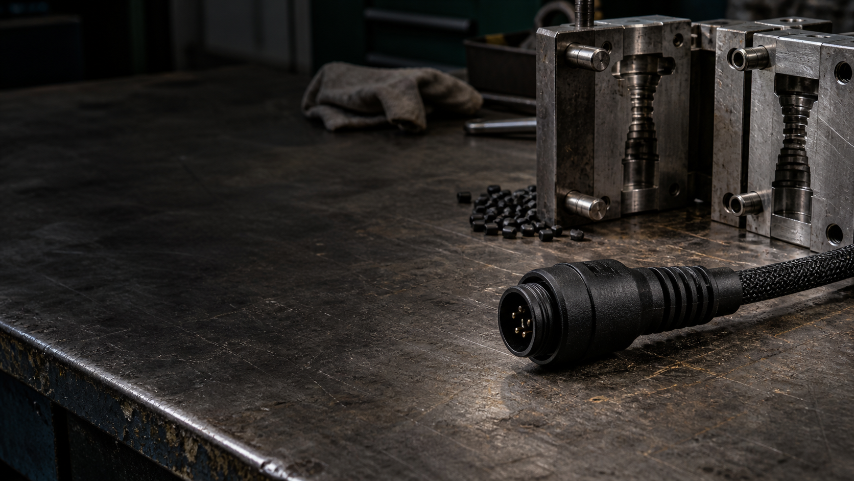
Molded connector and cable exit
A molded body stabilizes the termination and shapes a straight, side or angled cable exit. The design controls wall thickness, lock access, mating clearance and bend transition.
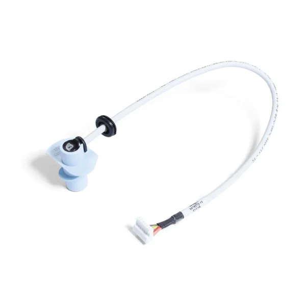
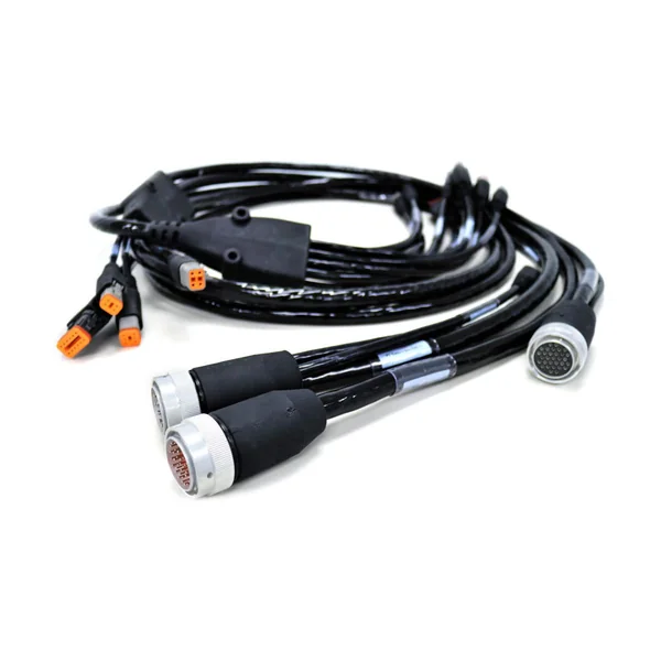
Overmolded cable assemblies encapsulate the connector-to-cable transition with a selected thermoplastic or elastomer to provide defined strain relief, sealing, touch protection, geometry and appearance. The result depends on the complete interface, cable jacket, molding material, insert preparation and process window.
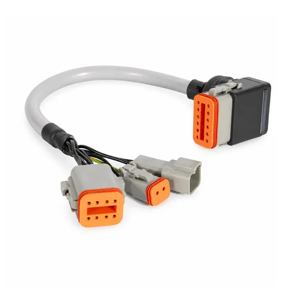
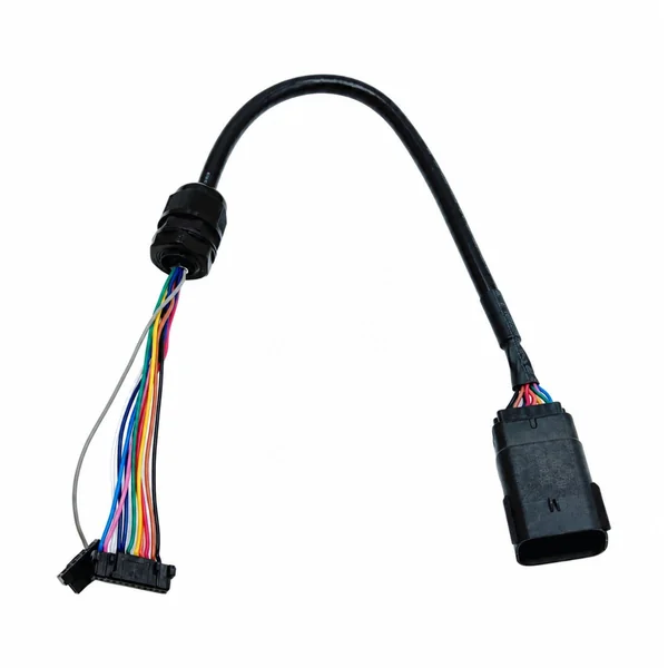
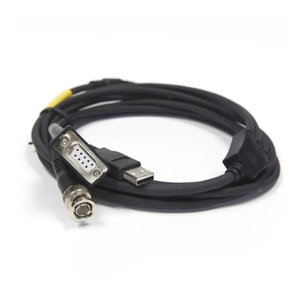
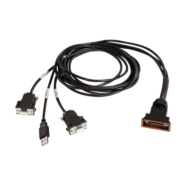
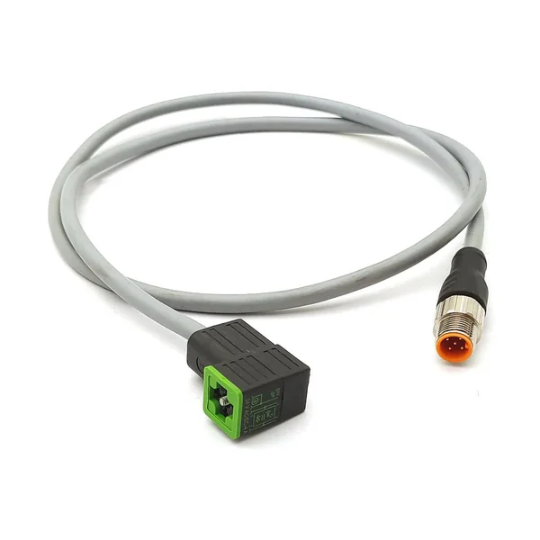
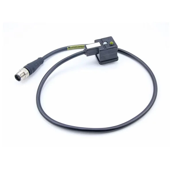
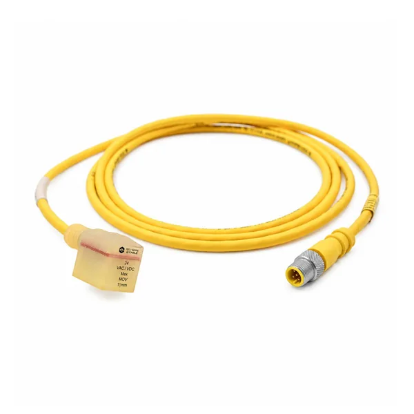
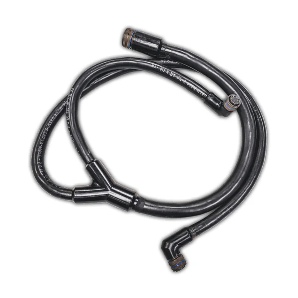
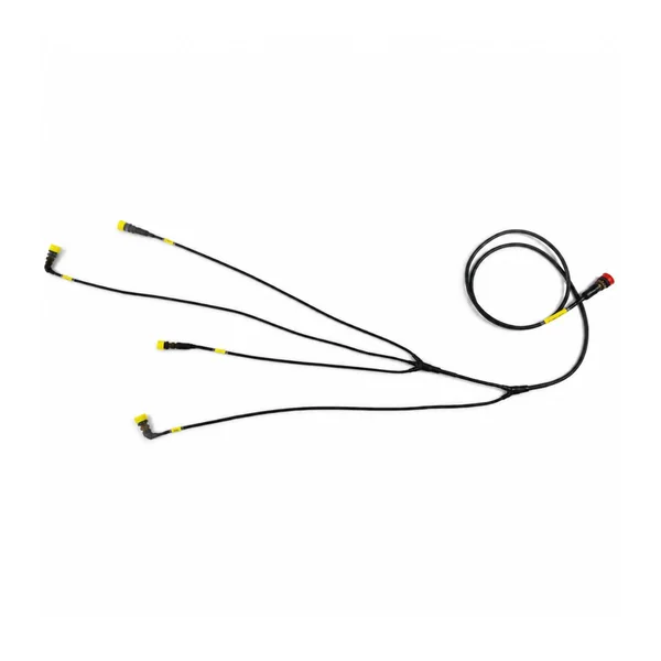
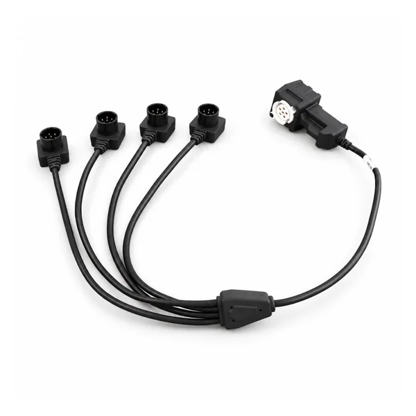
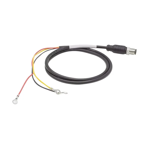
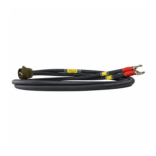
Connector protection, strain relief and molded geometry developed as one system
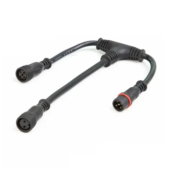
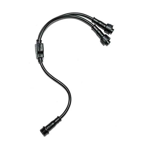
Overmolded cable assemblies cover far more than one connector style. They include straight or angled cable exits, soft strain-relief boots, hard shells, sealed junctions, molded branches, PCB or sensor encapsulation and two-shot constructions. The electrical termination is completed first, then the insert, cable jacket and molding resin are combined through a controlled tool and process. Material labels alone cannot predict adhesion, sealing or flex life, so geometry, preparation and validation must follow the actual assembly.
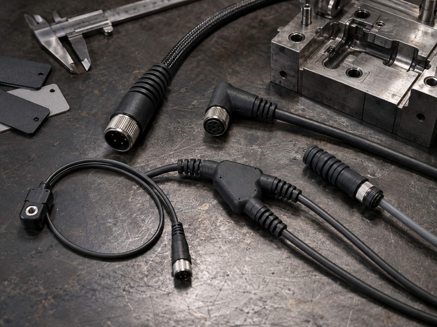
A molded body stabilizes the termination and shapes a straight, side or angled cable exit. The design controls wall thickness, lock access, mating clearance and bend transition.
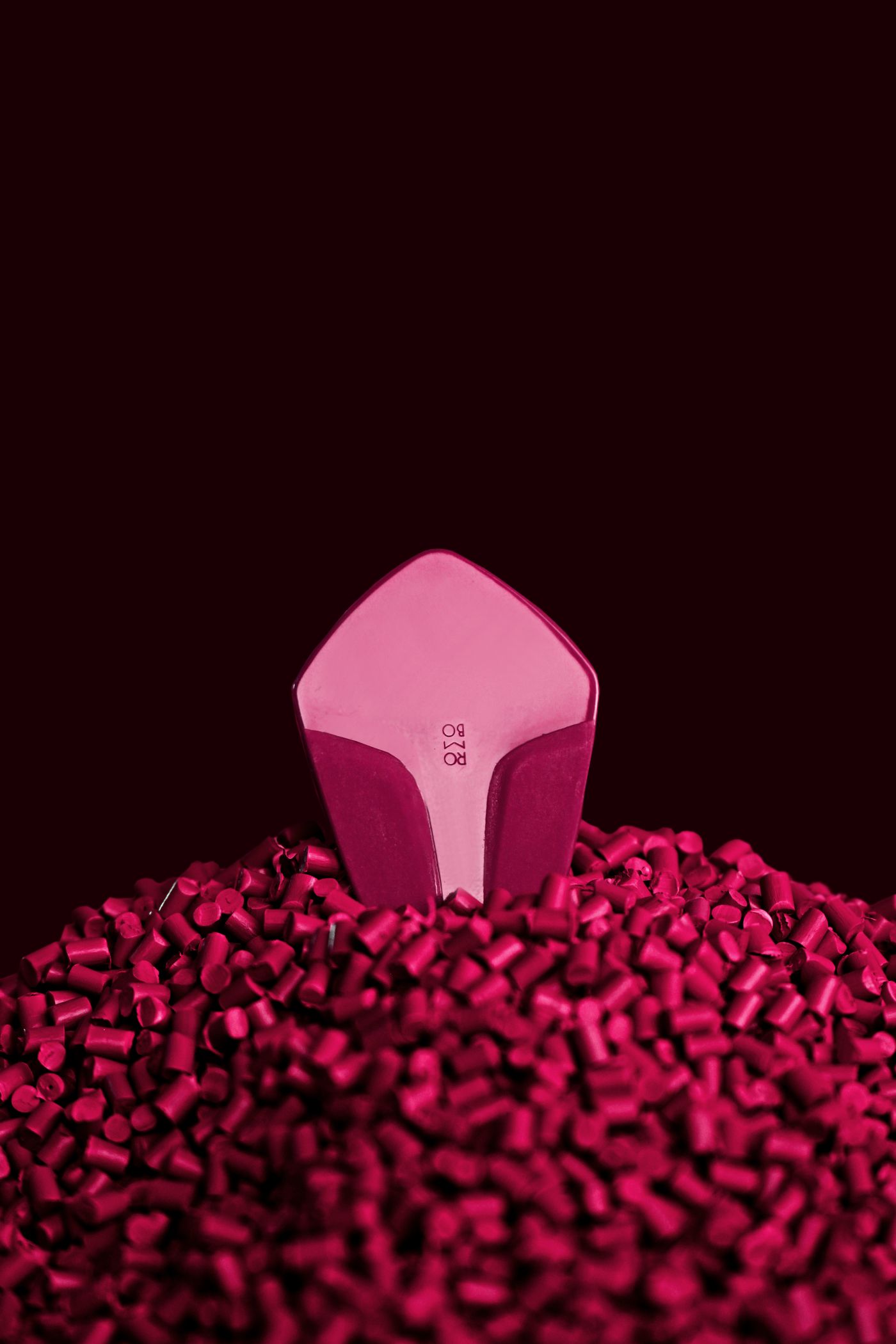
Flexible ribs or a tapered boot distribute bending away from the termination. Hardness, rib spacing, jacket grip and free cable length are tuned for the intended movement.
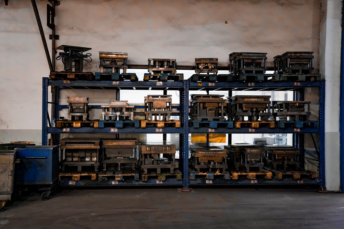
A rigid molded body can create handling surfaces, polarization, mounting features or touch protection while preserving the original mating interface and tolerances.
Splices, electronic components or multi-cable breakouts can be encapsulated when cavity filling, heat input, wire position and serviceability are reviewed.
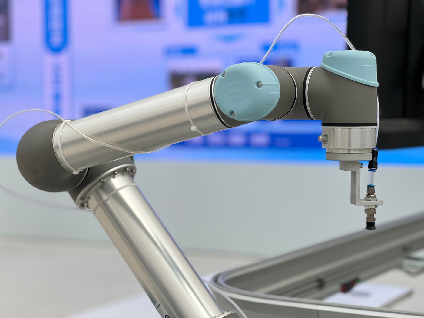
Sensitive boards, sensors or modules may use a low-pressure molding route to reduce component loading. Resin, board cleanliness, connector masking and heat exposure remain project specific.
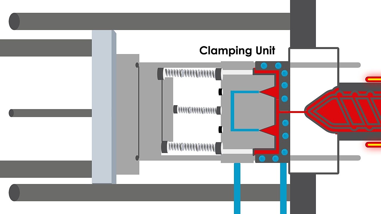
A hard or stabilizing pre-mold can secure terminals, shields and components before the final cosmetic or flexible layer is applied. The two materials need a compatible interface.
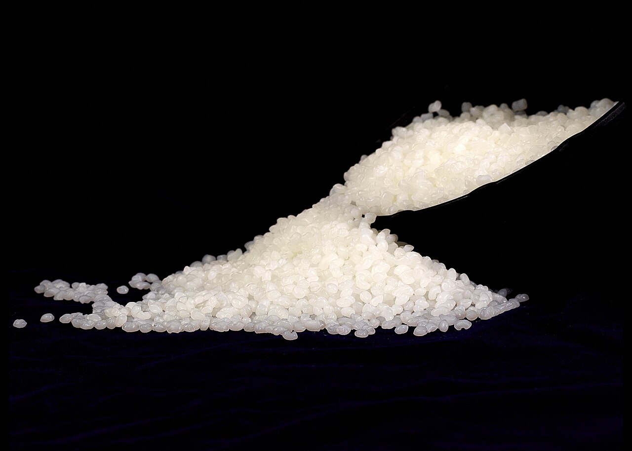
Current, voltage drop, signal function and crimp or solder geometry are confirmed before molding because the finished termination may no longer be accessible for correction.
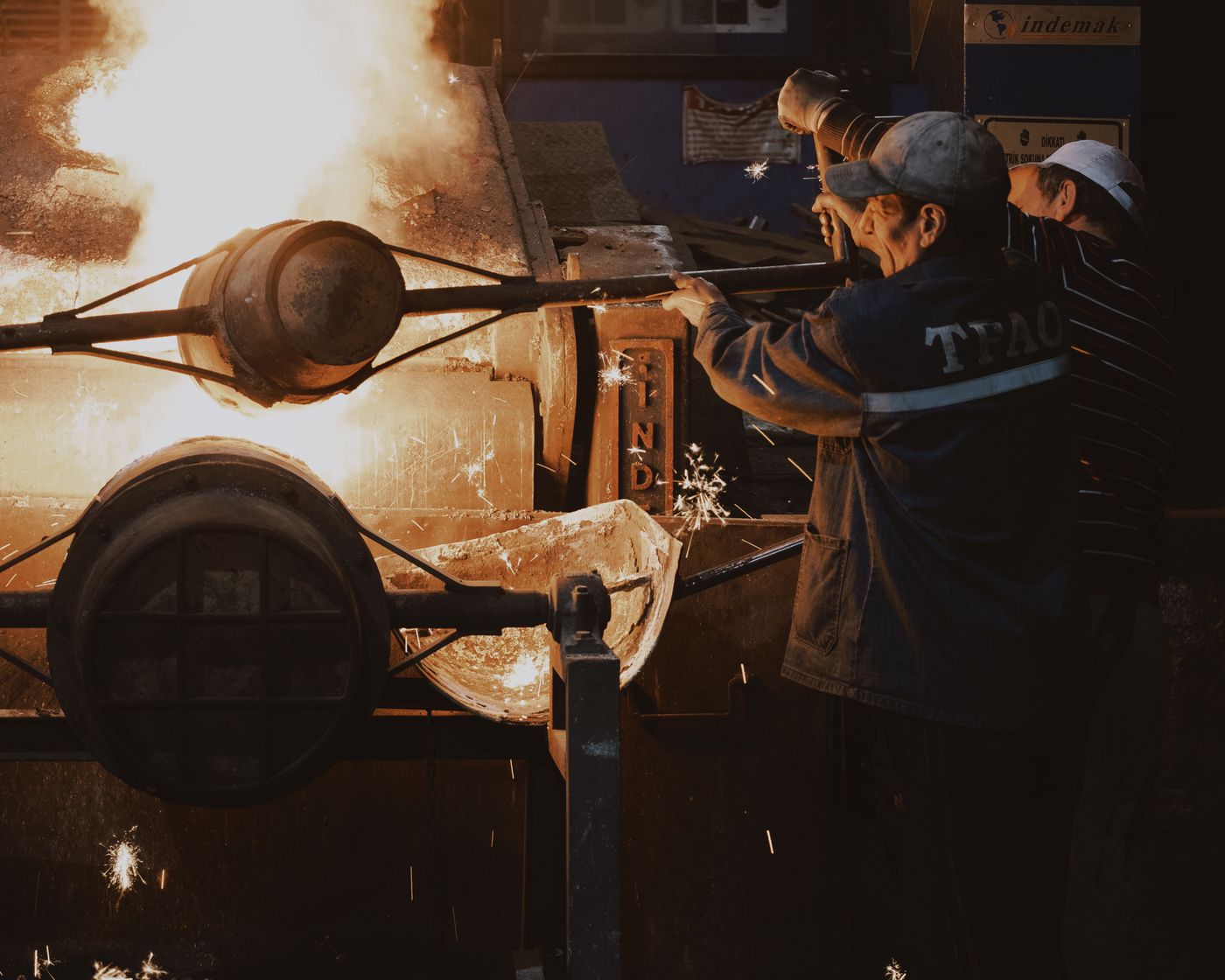
Metal and plastic inserts need retention features, clean surfaces and controlled clearances. Knurls, undercuts, holes or pre-mold geometry can provide mechanical locking when chemical adhesion is limited.
Material selection considers hardness, melt temperature, shrinkage, abrasion, oils, chemicals, UV, flammability and compatibility with the insert and cable jacket. No resin is universal.
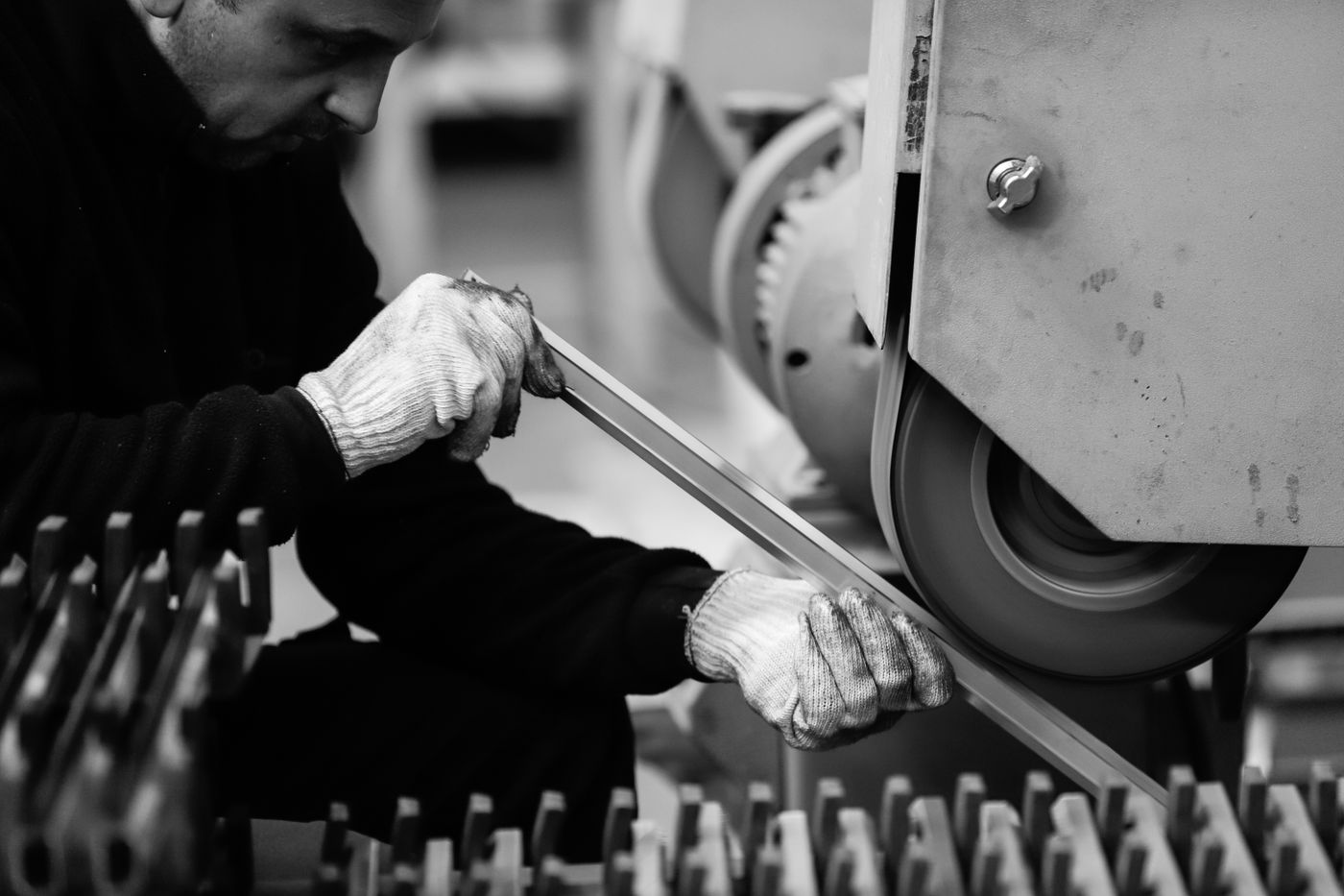
The cable jacket must tolerate molding heat and pressure without softening, distortion or migration. Surface energy and additives can also change adhesion to the overmold.
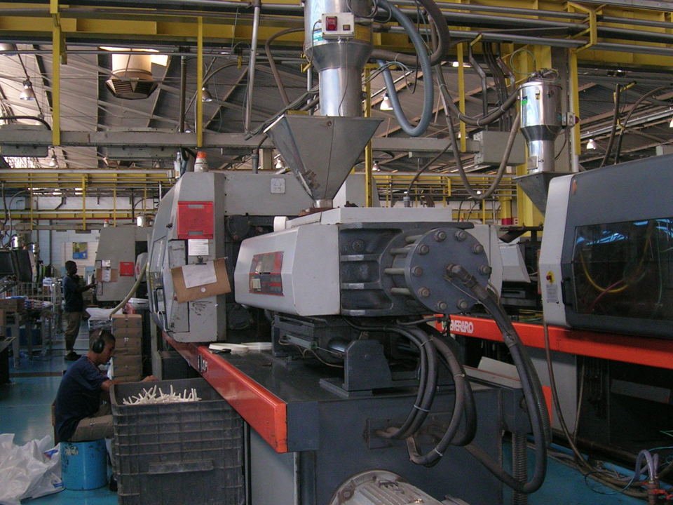
Mating clearance, user handling, cable pull direction, bending, sealing, chemicals and assembly space define the molded envelope before a tool is selected.

An existing tool may reduce development work only when insert position, cable diameter, interface clearance, gate, parting line and performance requirements genuinely match.
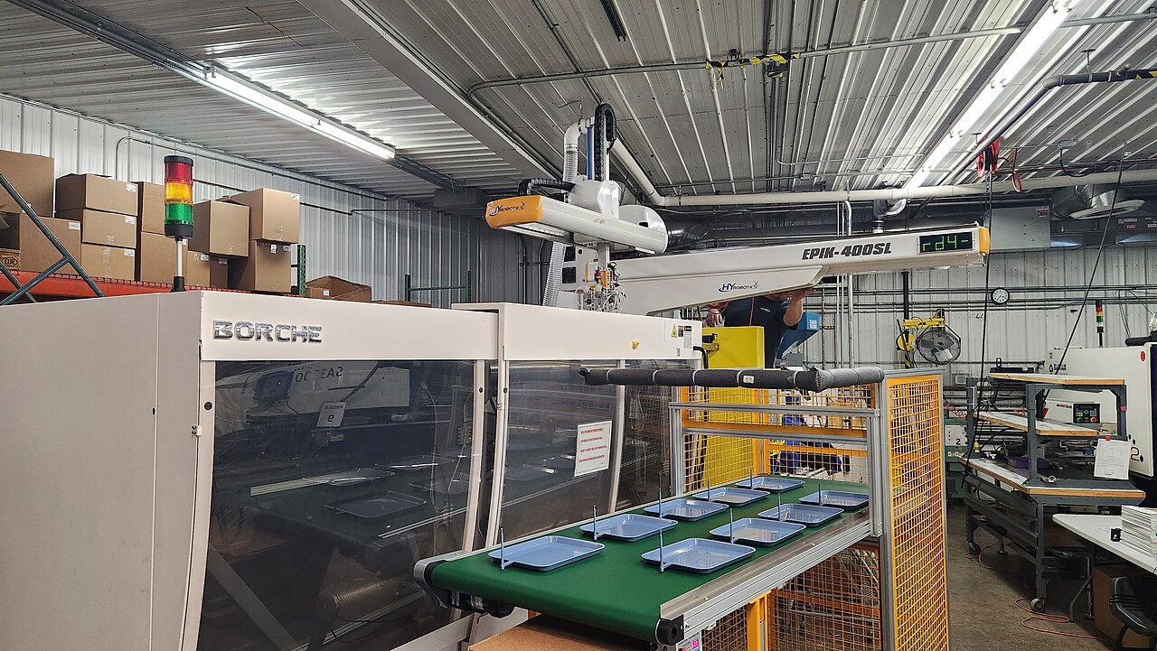
Fixtures support connectors, cables, shields and components against injection movement. Gate and vent locations are arranged to fill thin sections without trapping air or displacing wires.

Dimensions, continuity, mating, cable pull, bending, section cuts, sealing or environmental tests are selected according to the actual failure risks and agreed acceptance limits.
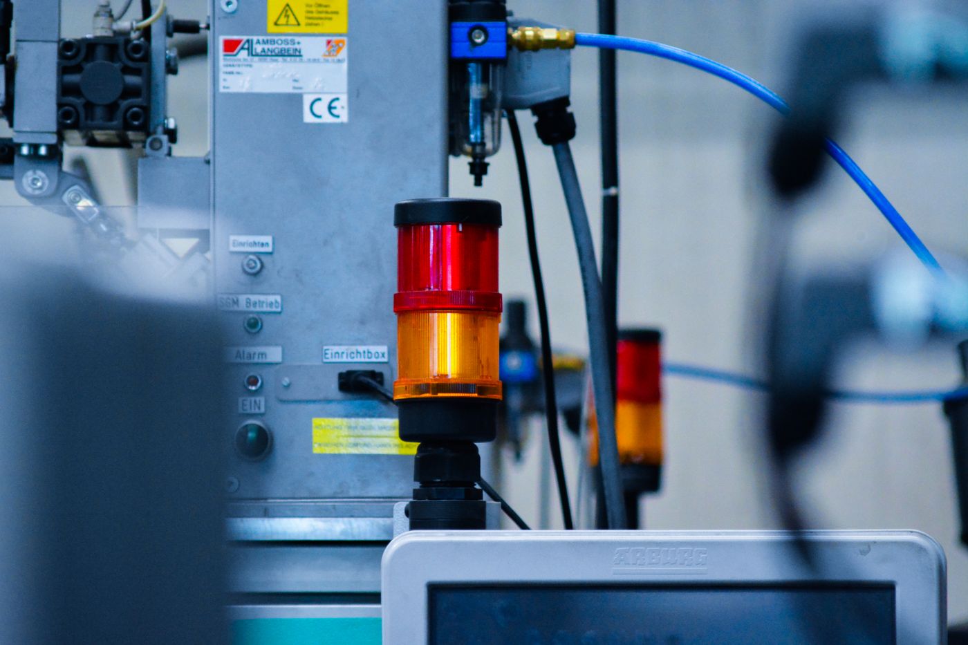
Overmolding can protect compact interfaces and cable exits on sensors, valves, switches and actuators exposed to handling, vibration or contamination.
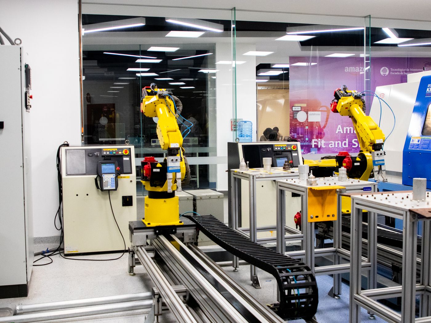
Molded connectors provide repeatable handling and strain relief for equipment modules, fixtures and replaceable station cables.
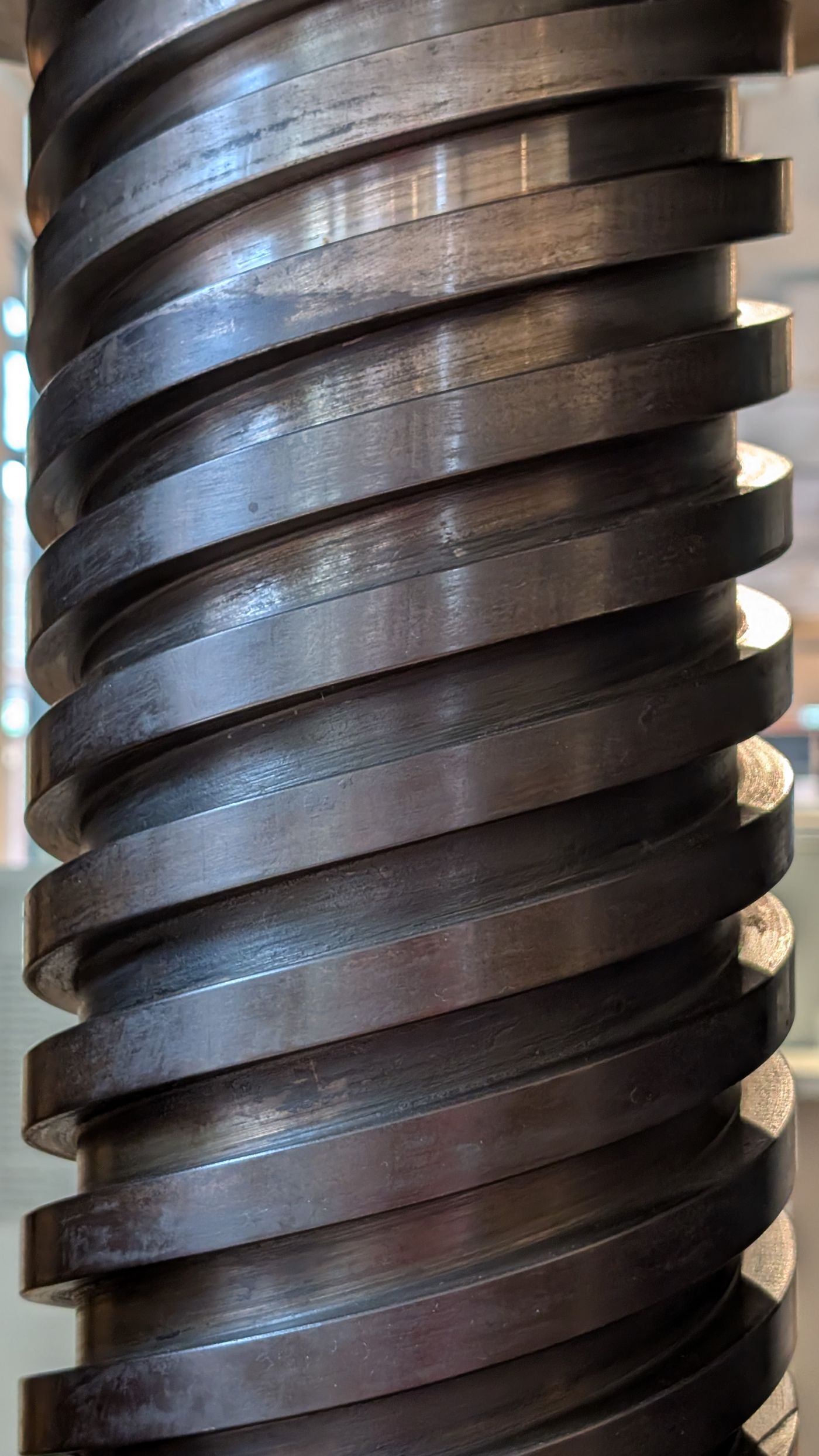
Defined boots and rigid bodies protect connectors around oil, chips, vibration and frequent technician handling when materials are matched to the exposure.
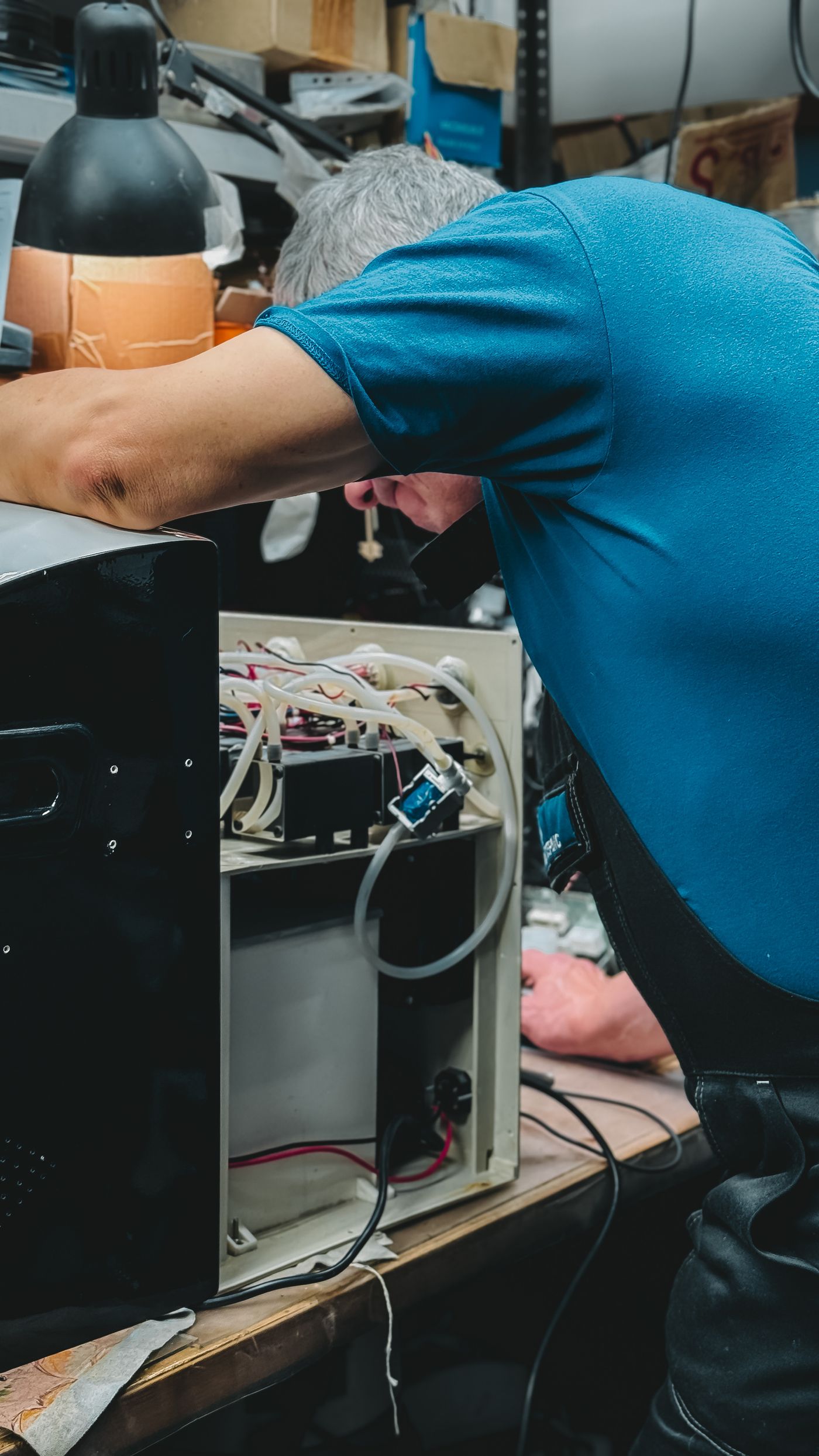
A tuned strain-relief transition can manage repeated cable movement, but flex life still depends on the cable, routing, bend radius and attachment system.
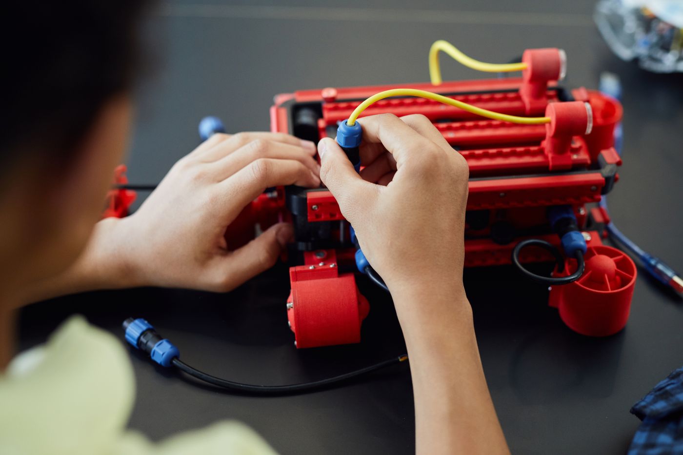
Molded junctions and plugs can combine touch protection, recognizable geometry, cleanability and repeatable assembly around motors, heaters and controls.
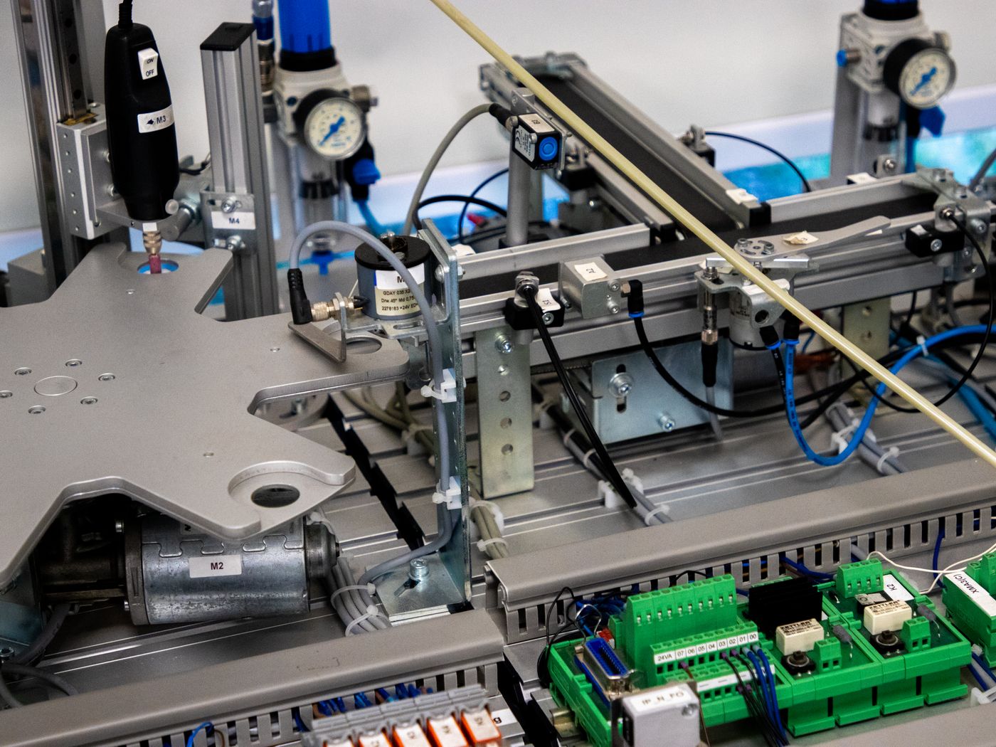
Custom exits, shield terminations and compact molded bodies support probes, instruments and fixtures when signal requirements and grounding are defined.
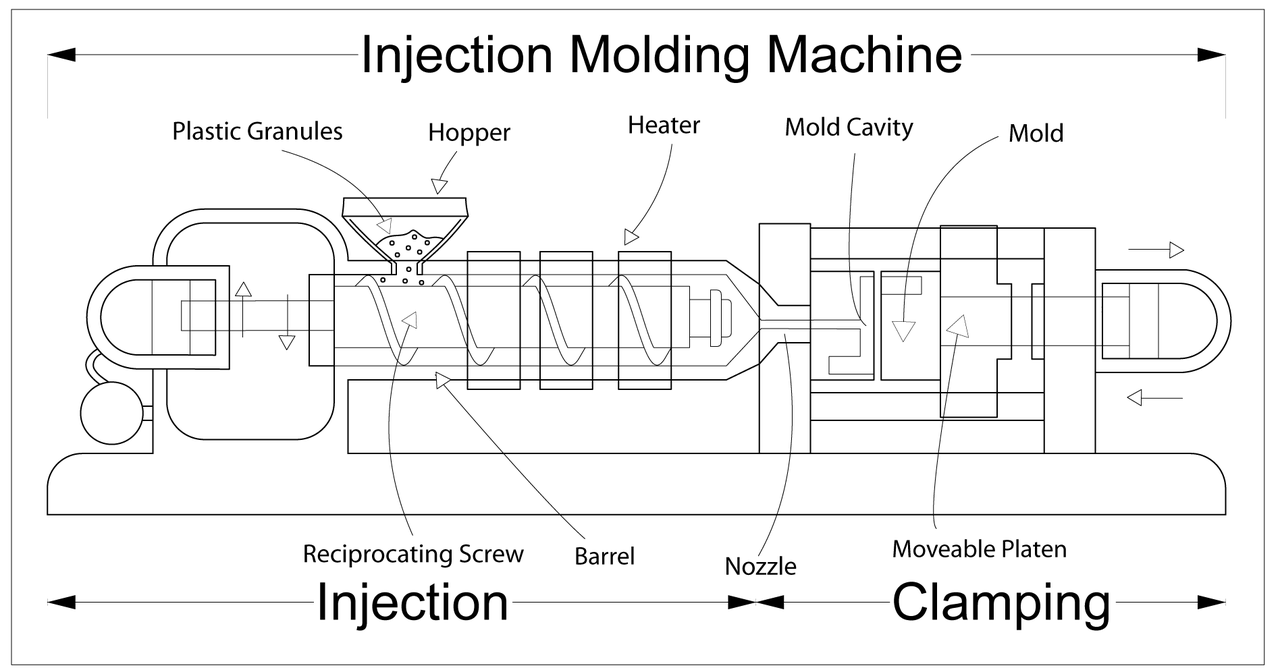
Confirm electrical function, interfaces, cable, molded geometry, environment, loads, colour, quantity, validation and any tooling constraints.
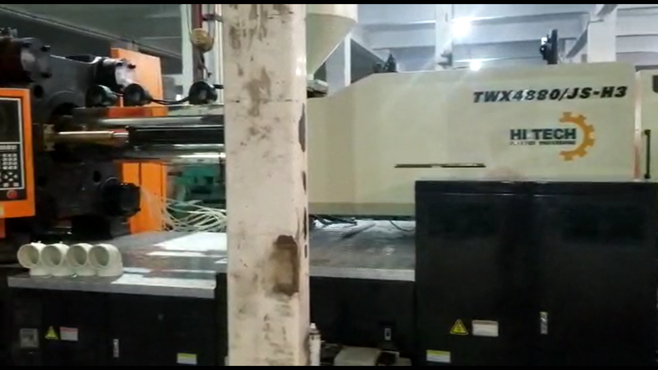
Define insert datums, cable exit, parting line, gate-sensitive faces, wall thickness, strain-relief profile, resin and inspection dimensions.

Complete crimping, soldering, splicing, shield termination and electrical checks, then stabilize and clean the insert for molding.
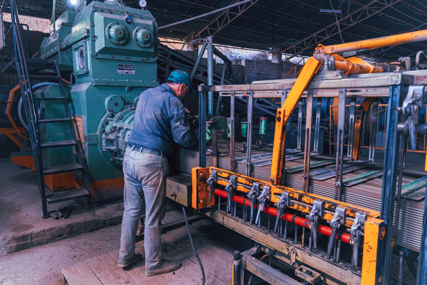
Set insert fixtures, temperature, pressure, speed, cooling and venting, then inspect short shots, flash, sink, cable movement and deformation on first pieces.
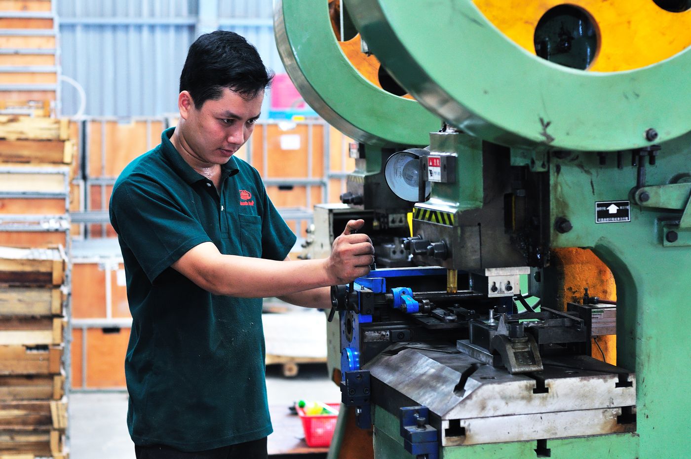
Check molded dimensions, mating, continuity, polarity and appearance plus agreed pull, bend, section, ingress or environmental items.
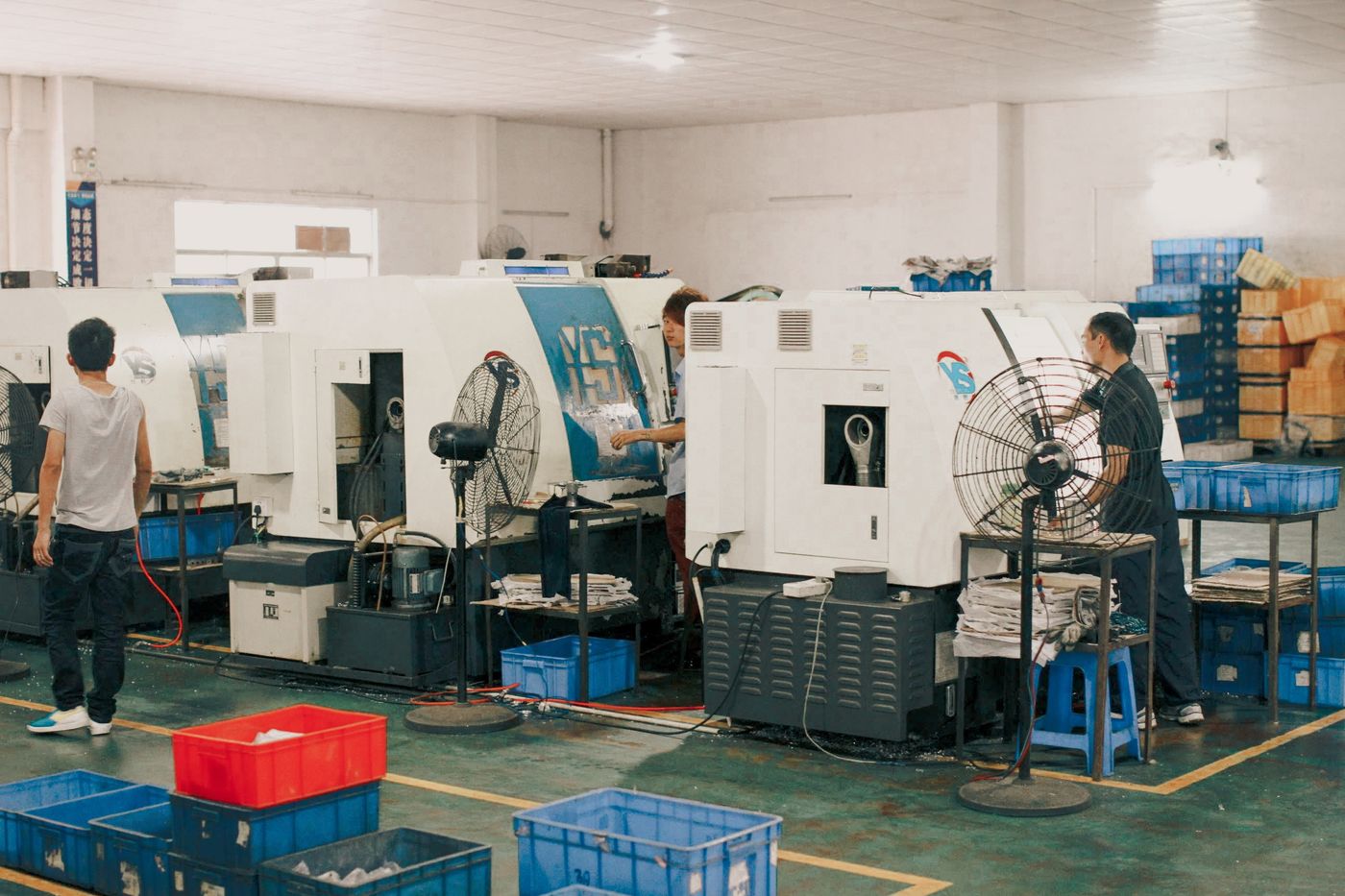
Release the approved drawing, BOM, tool setup, sample, work instruction and inspection plan as one controlled production reference.

Pull load and repeated bending can concentrate at the conductor termination if the boot is too stiff, too short or poorly bonded to the jacket.
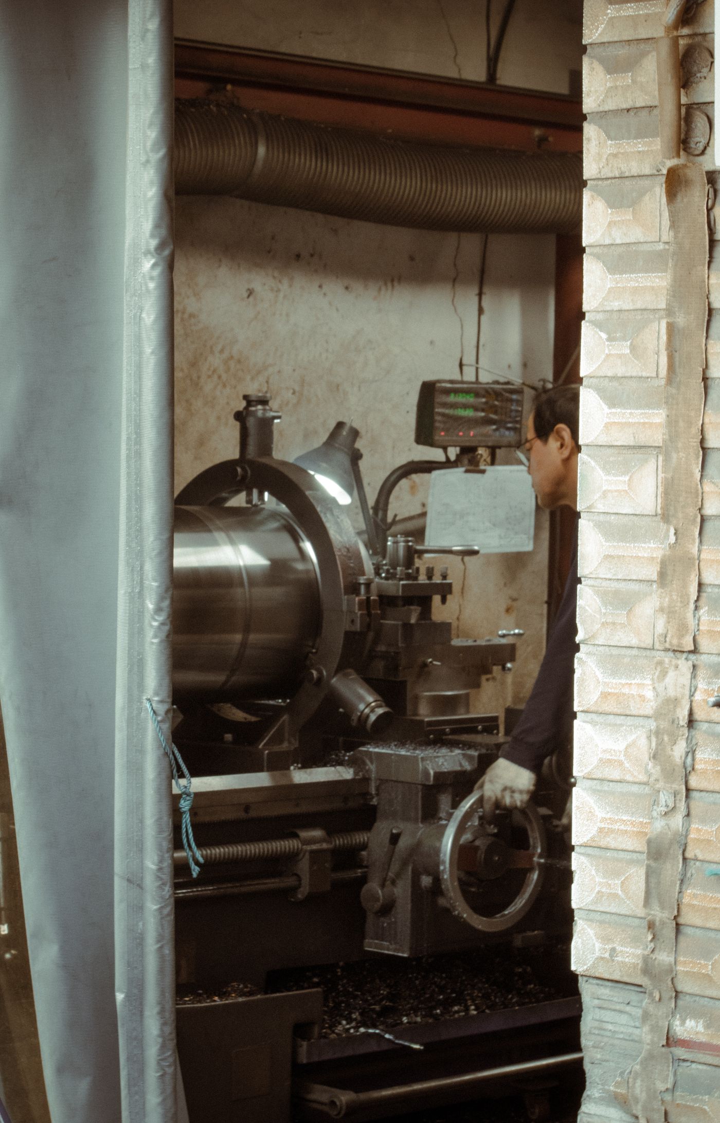
Oils, cleaners, water and plasticizer migration can change resin, jacket and interface behavior. Compatibility needs representative materials and conditioning.
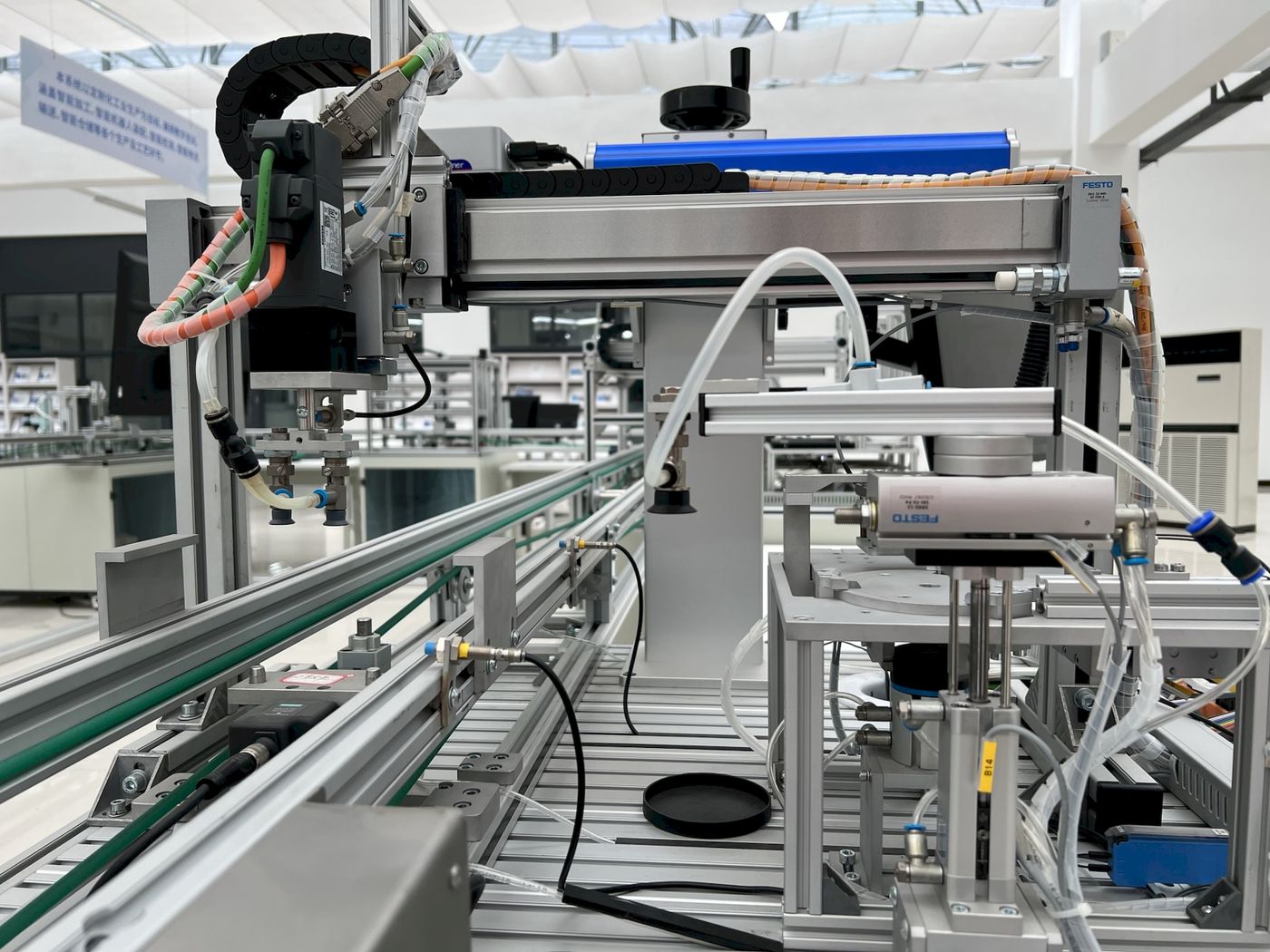
Heat, pressure and insert movement can disturb terminals, solder joints, shields or components, so post-mold electrical checks remain mandatory.

Overmolding can support sealing, but any ingress, temperature, flame or endurance claim requires a defined specimen, method and acceptance limit.
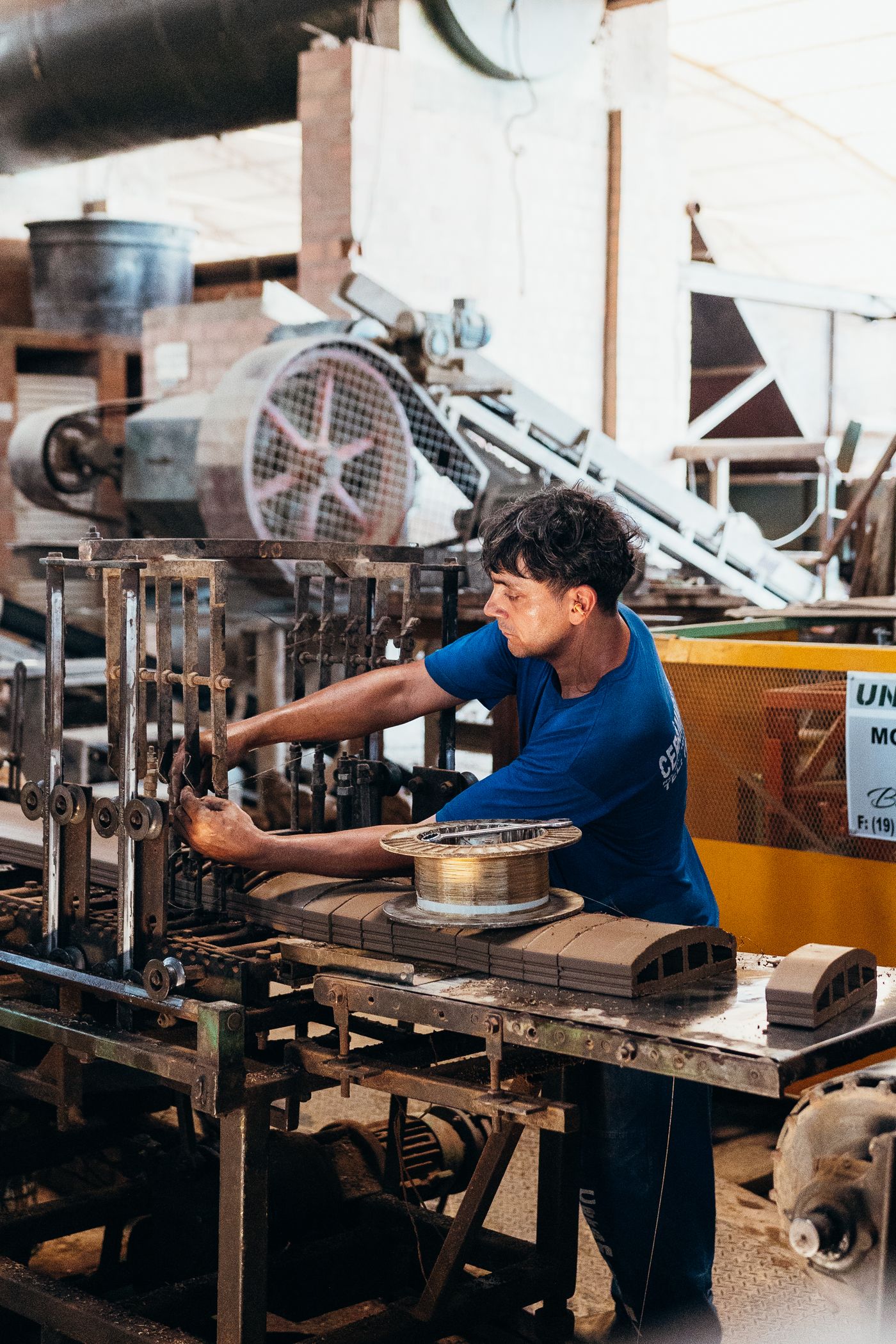
Controlled molded geometry distributes handling and bending loads while protecting the internal termination from direct contact.
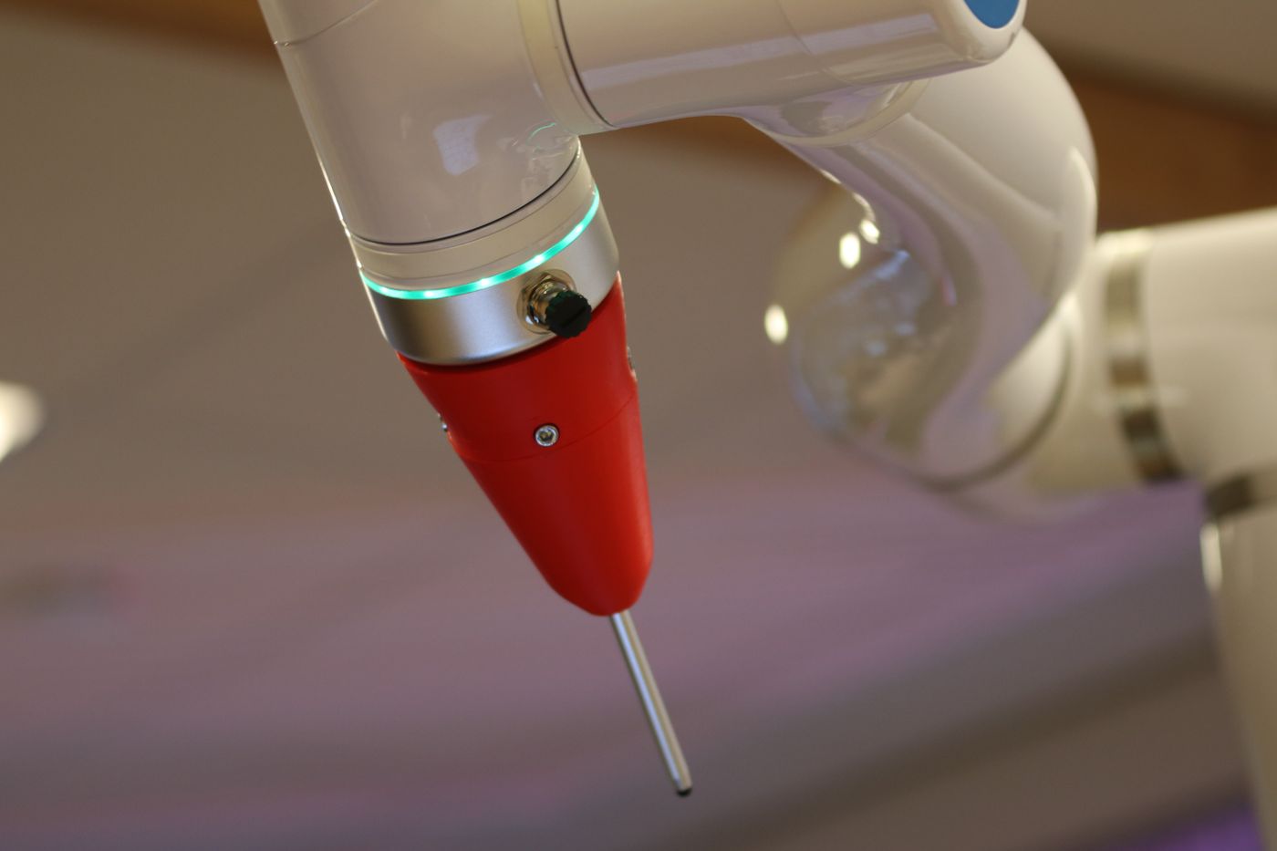
Tool-controlled exits, keys, grips and mounting features reduce assembly ambiguity across repeated builds.
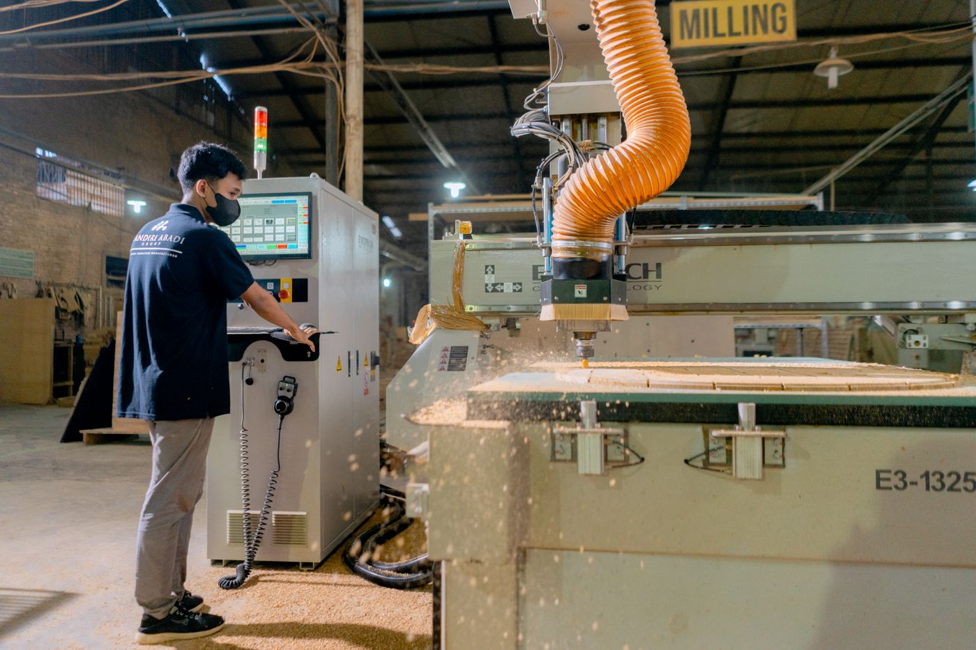
Suitable processes can combine insulation, component support, touch protection and environmental covering within a compact envelope.

Electrical assembly, material set, tool, process settings, dimensions and inspection points are released together instead of treating molding as decoration.
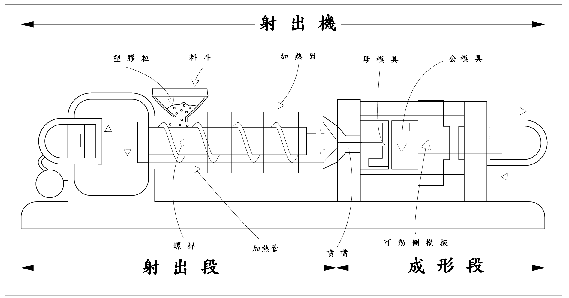
Overmolding forms material directly around the insert and cable in a tool, creating a controlled integrated geometry. A separate boot is assembled afterward and may not provide the same retention, sealing or dimensional control.
The choice depends on hardness, flexing, temperature, chemicals, abrasion, flame requirements, colour, cable-jacket compatibility and processing temperature. A material name alone is not enough.
Possibly, after insert position, cable diameter, interface clearance, exit direction, parting line, gate and required performance are compared. Similar appearance does not guarantee fit.
No. Sealing depends on the complete interface, material compatibility, cable jacket, insert geometry, molding quality, mating condition and the agreed test configuration.
Provide connector and insert data, pin map, cable construction and diameter, molded dimensions, exit direction, material or hardness target, environment, quantity and required validation. A physical sample can support review.
Finished assemblies receive continuity and appearance inspection plus dimensional, mating, lock, flash, deformation and other agreed checks. Pull, bend, ingress or environmental tests follow the approved project plan.
PART NUMBER / INTERFACE / MATERIAL
Find a cable model or material part number, then send it for a custom replacement or original-part sourcing review.
No matching references. Try a brand, full part number or a listed alias.
Finished cable and harness references for this interface or application.
Overmolded rectangular cable assembly
Custom compatible replacements · Original-parts sourcing
Overmolded rectangular cable assembly
Custom compatible replacements · Original-parts sourcing
Overmolded rectangular cable assembly
Custom compatible replacements · Original-parts sourcing
Overmolded rectangular cable assembly
Custom compatible replacements · Original-parts sourcing
Overmolded rectangular cable assembly
Custom compatible replacements · Original-parts sourcing
Overmolded rectangular cable assembly
Custom compatible replacements · Original-parts sourcing
Overmolded rectangular cable assembly
Custom compatible replacements · Original-parts sourcing
Overmolded rectangular cable assembly
Custom compatible replacements · Original-parts sourcing
Overmolded rectangular cable assembly
Custom compatible replacements · Original-parts sourcing
Overmolded rectangular cable assembly
Custom compatible replacements · Original-parts sourcing
Overmolded rectangular cable assembly
Custom compatible replacements · Original-parts sourcing
Overmolded rectangular cable assembly
Custom compatible replacements · Original-parts sourcing
Overmolded rectangular cable assembly
Custom compatible replacements · Original-parts sourcing
Connector, wire and process-material references for project selection.
TPE grade for medical cable jackets and molded connectors
Custom compatible replacements · Original-parts sourcing
Cable wire material
Custom compatible replacements · Original-parts sourcing
TPE grade for medical cable jackets and molded connectors
Custom compatible replacements · Original-parts sourcing
Cable wire material
Custom compatible replacements · Original-parts sourcing
TPE grade for medical cable jackets and molded connectors
Custom compatible replacements · Original-parts sourcing
Cable wire material
Custom compatible replacements · Original-parts sourcing
TPE grade for medical cable jackets and molded connectors
Custom compatible replacements · Original-parts sourcing
Cable wire material
Custom compatible replacements · Original-parts sourcing
Cable wire material
Custom compatible replacements · Original-parts sourcing
Cable wire material
Custom compatible replacements · Original-parts sourcing
Confirm connector part numbers, latch travel, keying and space that the mold must leave clear.
Select the mold resin with the actual cable jacket and insert materials; verify adhesion on assembled samples.
Define exit angle, supported length, bend clearance and the cable pull direction at installation.
Review gate location, insert positioning, molding pressure and thermal exposure against the connector limits.
Specify the required sealed interfaces and test the completed assembly in its actual mating state.
Approve molded dimensions, flash limits, pin mapping and electrical tests before releasing the tooling revision.
Send the part number, drawing or sample to confirm the replacement configuration and sourcing plan.
PROJECT REVIEW / CUSTOM MANUFACTURING
Custom wire harness manufacturing from our China factory, with OEM/ODM project support.
A sample, clear connector photos or a description of the equipment and required quantity is enough to start a review.