
Product type

Agricultural & Tractor Harness

Overview

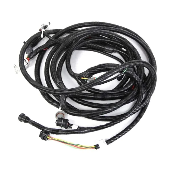
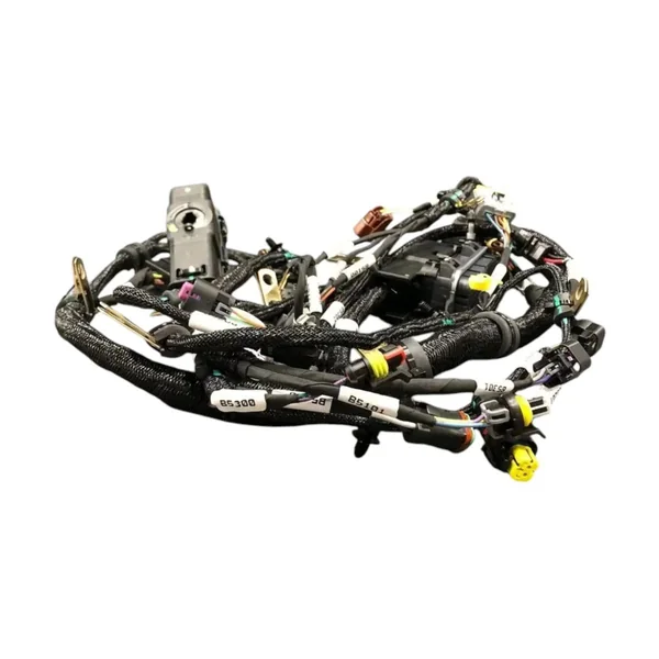
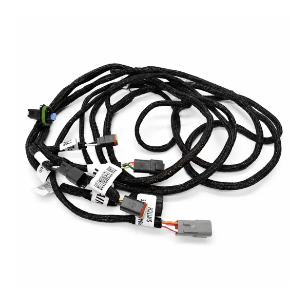
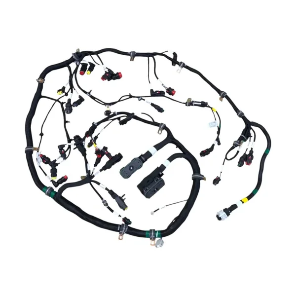
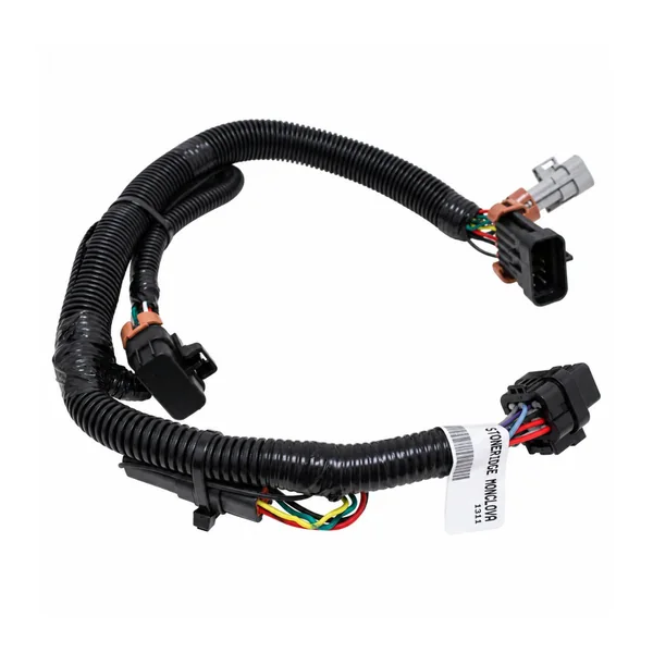
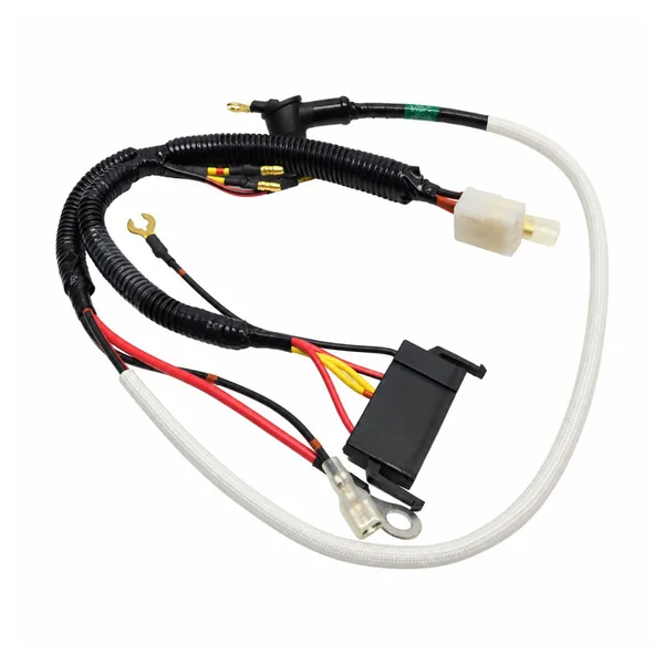
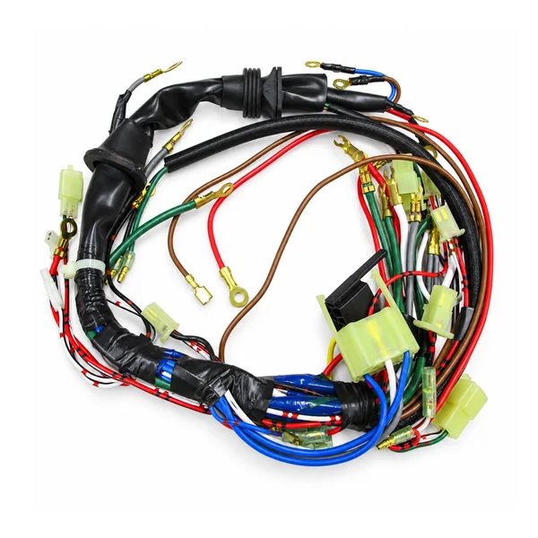
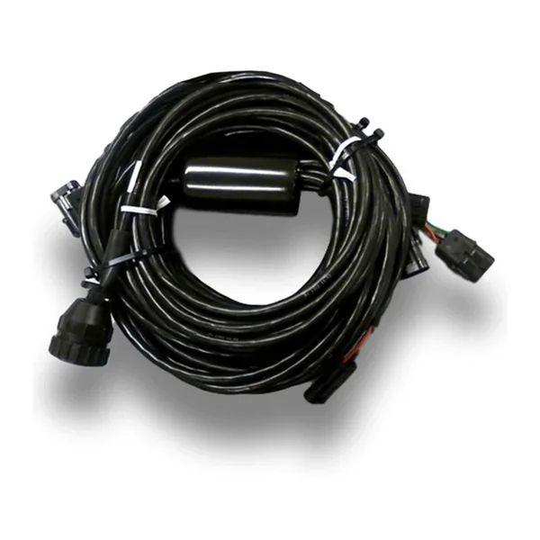
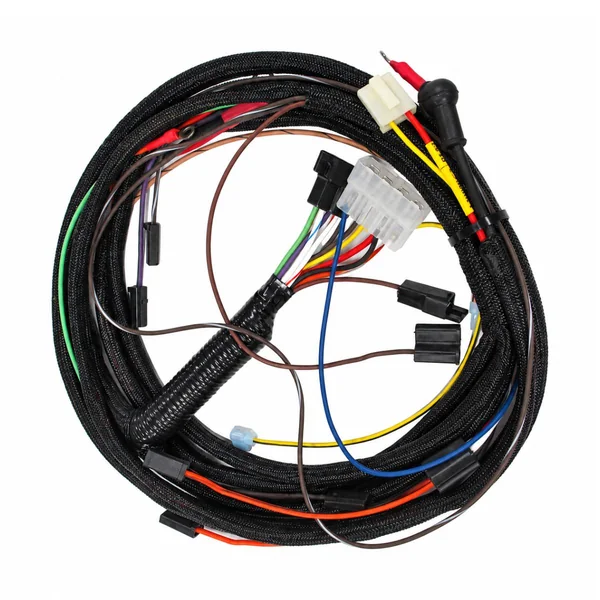
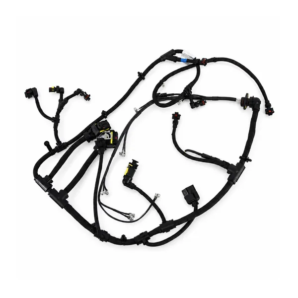
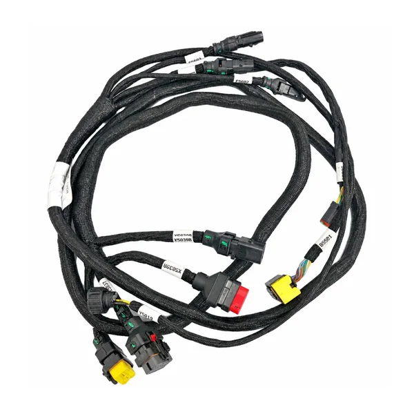
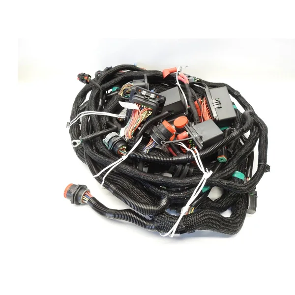
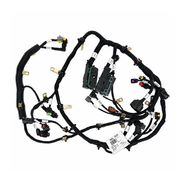
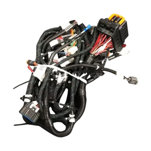
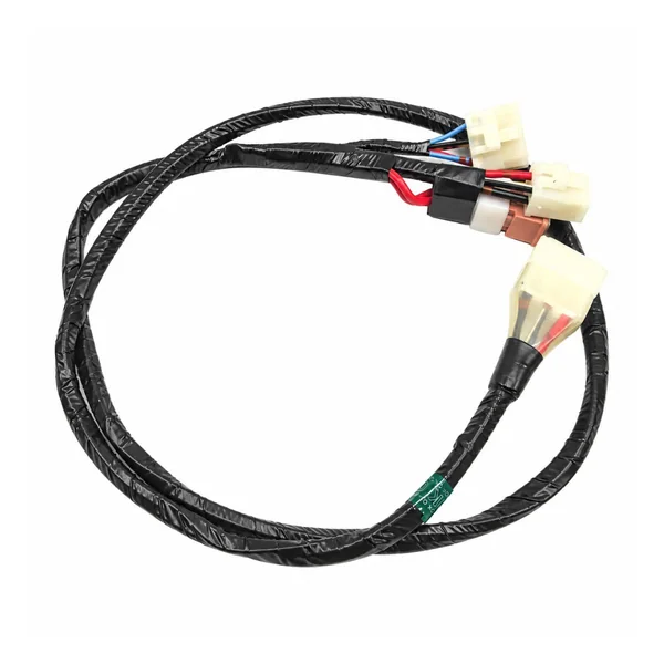
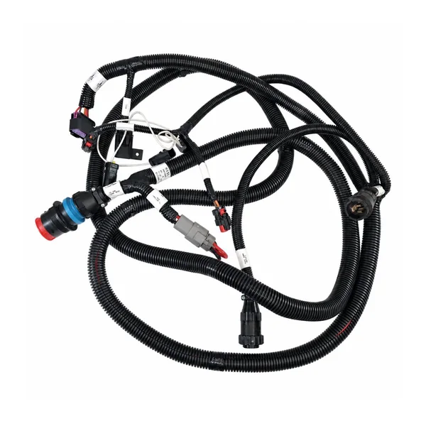
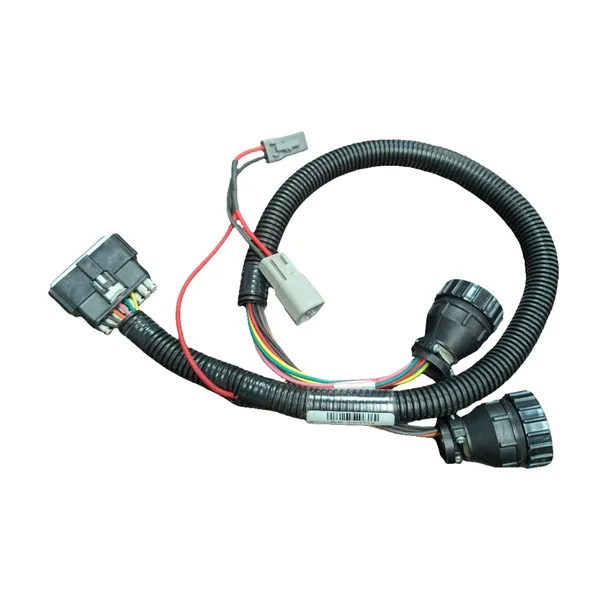
Agricultural and tractor wiring harnesses cover cab controls, engine and chassis circuits, lighting, sensors, implements and field-service connections. We develop each main loom or replaceable branch from the actual machine, interface schedule and working environment—not a generic tractor outline.

Agricultural & Tractor Harness - Automotive
FIELD / MACHINE / INTERFACE / SERVICE

One machine, many electrical zones

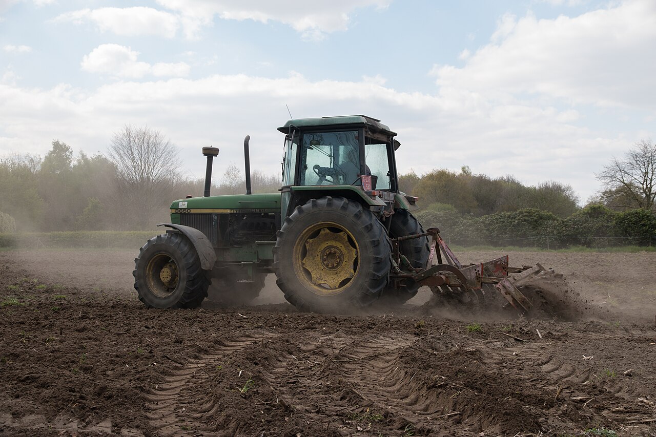
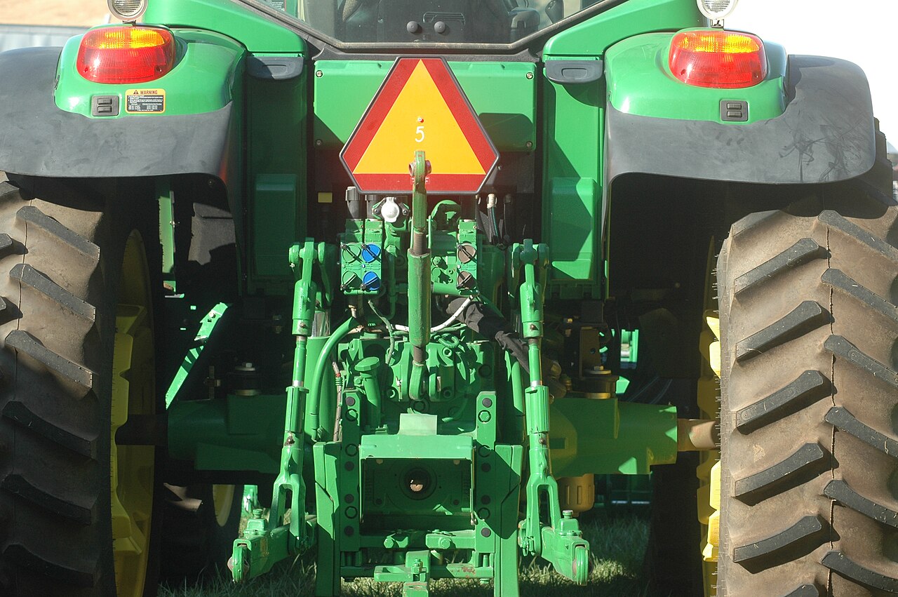
A cab loom, engine branch, rear-implement lead and lighting harness can all belong to the same tractor, yet need different connector, protection and service decisions. The useful starting point is the exact machine configuration and what each circuit must do in the field.

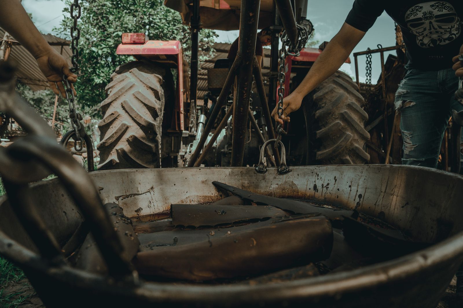
Agricultural & Tractor Harness rear implement context
01

HARNESS FAMILIES

Separate cab, powertrain, chassis and implement branches
Separate cab, powertrain, chassis and implement branches

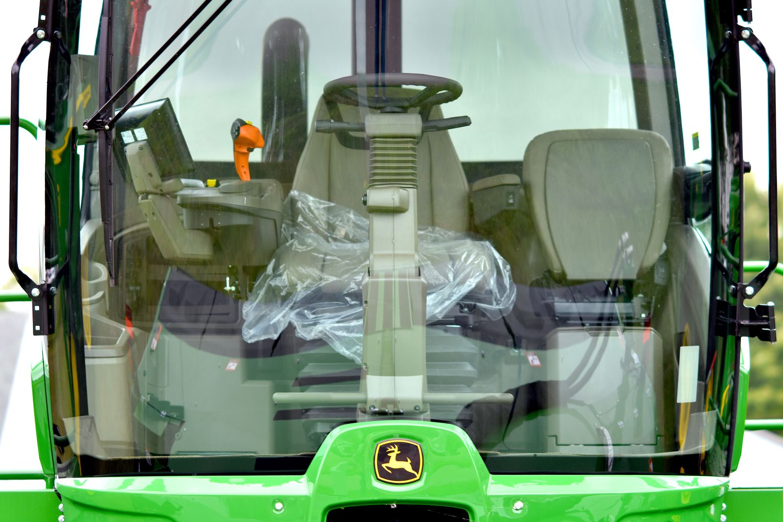
Cab panels, displays, switches and HVAC favor accessible routing and clear labeling. Engine and transmission branches encounter heat, oil and movement; chassis runs face stones, wash water and suspension travel. Rear lighting, trailer and implement connections may be unplugged regularly. A complete machine loom can be divided into serviceable modules, but every interface needs a released cavity map, polarity, mating direction and length datum. Tractor, combine and sprayer projects therefore share a method, not a universal wire harness.

Build by electrical zone

Main, cab, engine, chassis, lighting and implement branches can be quoted separately or as a controlled set.

Preserve service boundaries

Place disconnects where an operator or technician can actually reach and identify them.
02

FIELD EXPOSURE

Mud, spray and vibration are installation problems, not adjectives

Mud, spray and vibration are installation problems, not adjectives

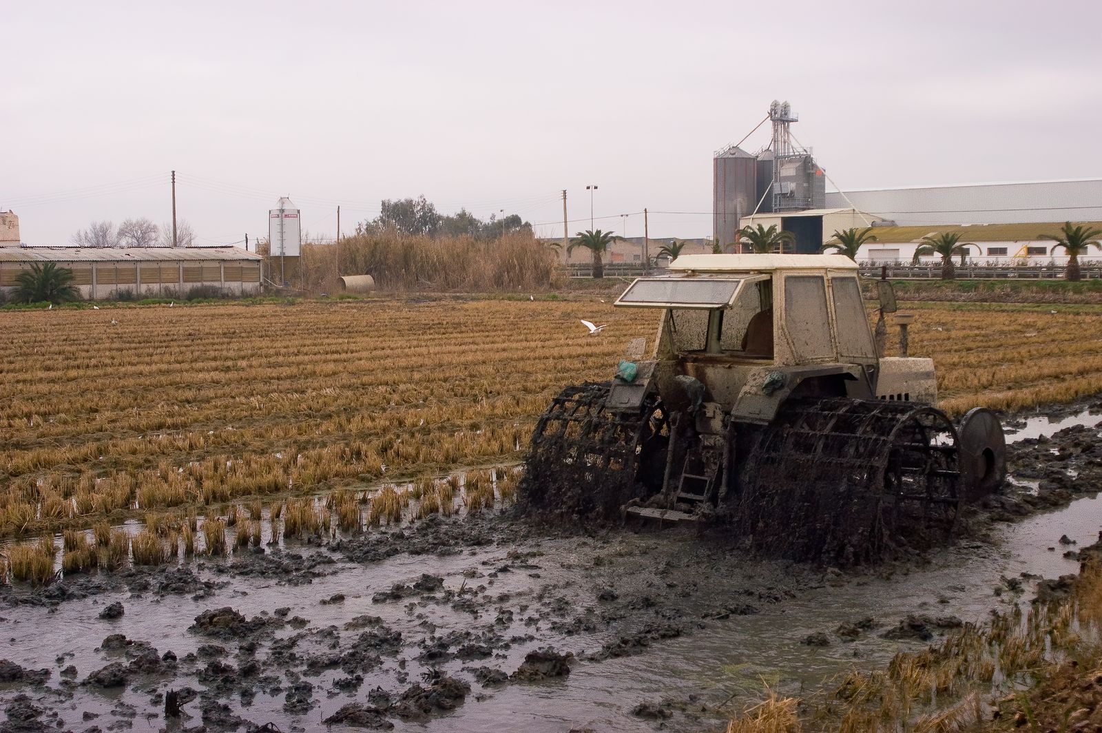
Agricultural equipment may cross wet soil, dusty fields and chemical-spray areas in one season. Exposure differs between a sheltered cab, a wheel arch and a rear hitch. Specify connector location, mating seal, individual wire seals, blind plugs for unused cavities, backshell exit, drainage direction, abrasion sleeve and support spacing for each zone. A component IP marking applies only to its defined mated and installed condition; it does not certify the finished harness or machine. UV, fertilizer and washdown compatibility likewise require the selected materials and agreed test method.

Route above the splash path

Keep joints and service loops away from standing water and moving tyres where layout allows.

Do not infer a seal

The plug, wire diameter, seal, cavity fill and mating half must form one specified system.

03

WIRE & PROTECTION

Choose conductor and covering by load, heat and motion

Choose conductor and covering by load, heat and motion

Starting, charging, lighting, valve coils, sensors and CAN circuits do not have the same current or noise requirements. Wire size follows load, voltage drop, protection device and termination range. Fixed zones and articulated or flexing zones may need different conductor constructions. PVC, cross-linked insulation, corrugated tube, braided sleeve and heat protection are options—not a substitute for locating the actual hot surfaces, oil sources, bend points and clamp positions. Keep sensitive signals away from high-current switching paths where the equipment design requires it.

Size the complete circuit

Include return path, connector contacts, fusing and duty cycle rather than wire diameter alone.

Protect at transitions

Sleeve ends, branch exits and clips are common abrasion and bending concentration points.

04

IMPLEMENT INTERFACE

ISOBUS is a system question, not just a socket shape

ISOBUS is a system question, not just a socket shape

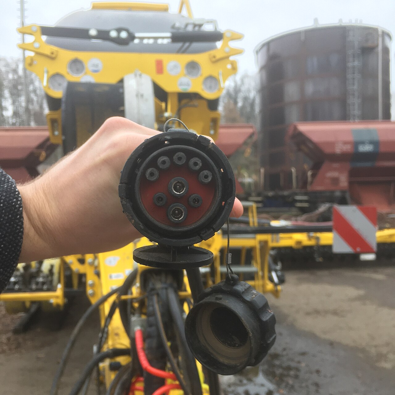
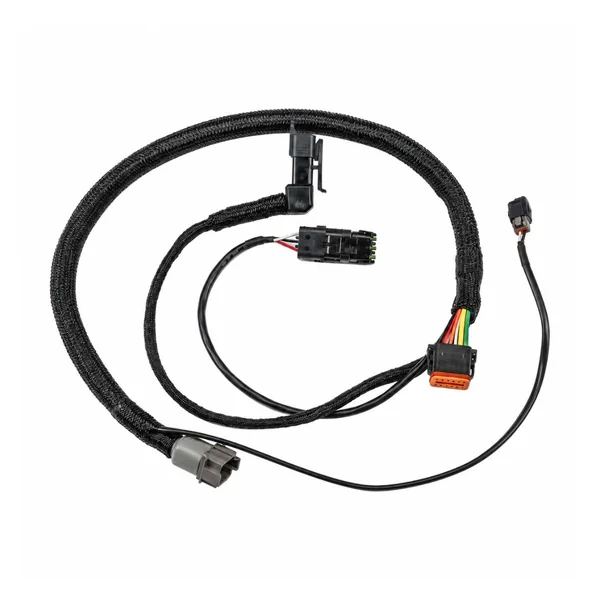
ISO 11783 defines a family of agricultural data-network specifications; AEF describes interoperable functions and test programs across machines and implements. A tractor-to-implement lead therefore needs the specified connector pair, contact and power allocation, bus conductors, shield and termination plan, length, strain relief and rear-hitch routing. But fitting the physical plug cannot promise Universal Terminal, Task Controller or any other AEF function. The tractor, implement, software and required function set need separate compatibility evidence. The photo illustrates an implement-side socket, not a Super Smile finished assembly.

Define both mating halves

Contact count, keying, cavity view, supply and bus assignment are drawing inputs.

Separate physical from functional fit

Continuity or a mating plug alone does not establish ISO 11783 interoperability.

05

MACHINE APPLICATIONS

Tractor, combine and sprayer projects change the branch map

Tractor, combine and sprayer projects change the branch map

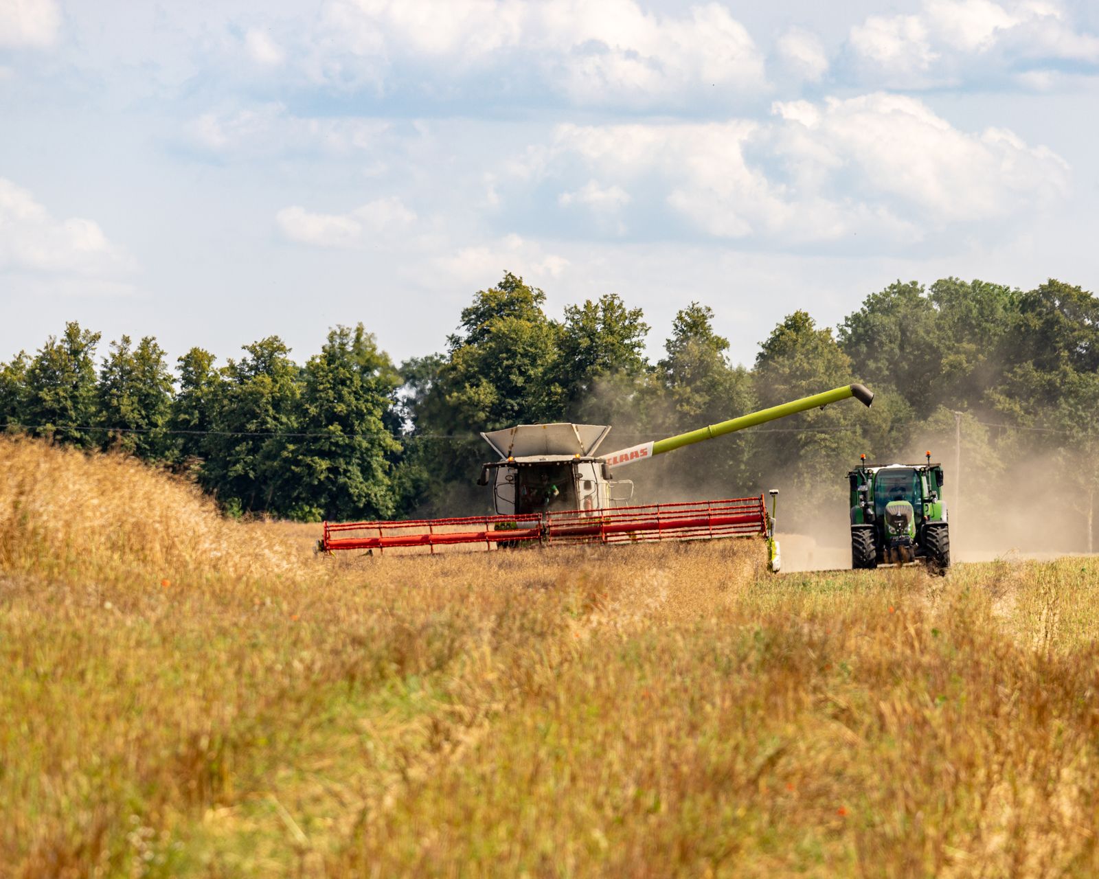
A field tractor may emphasize cab controls, engine management, rear work lamps and detachable implements. A combine adds long runs to headers, grain handling, monitoring sensors and actuators. Sprayers may add valves, pumps, section control, flow and pressure sensing, and exposure to cleaning or agricultural chemicals. These are application examples, not claims that one stock loom fits every machine. The machine model, attachment options, controller architecture and maintenance plan decide what belongs in each custom assembly.

Option content matters

Lighting, guidance, implements and cab equipment can change cavity population and branch length.

Reference the real route

Installation photographs and datum dimensions prevent a correct circuit from becoming an unfit loom.

06

BUILD & INSPECTION

Release the pin map before repeating the build

Release the pin map before repeating the build

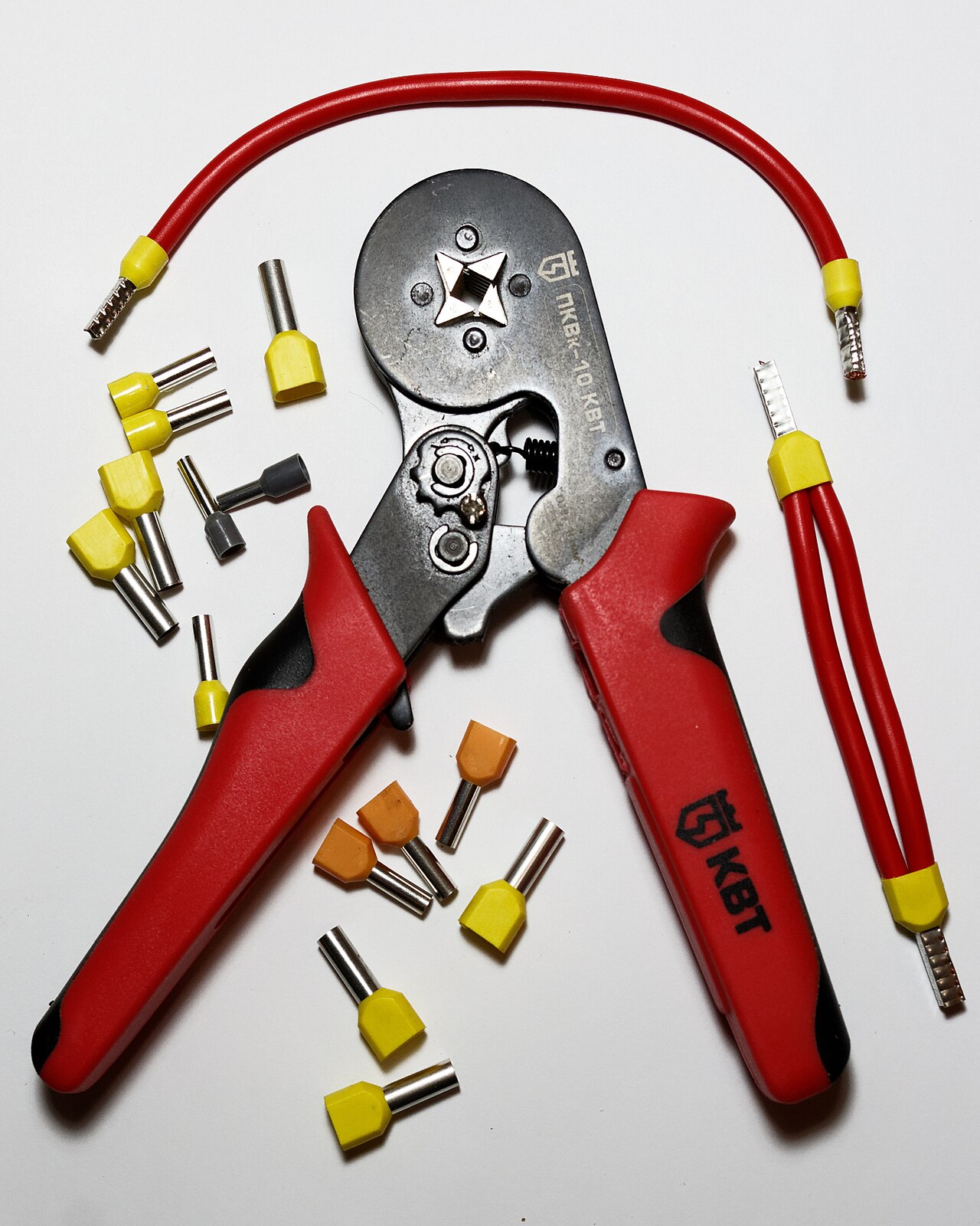
The work package should identify the drawing revision, BOM, cut lengths, branch datums, connector and terminal numbers, wire seals, cavity plugs, crimp tooling, covering and labels. A first article checks length, breakout direction, connector orientation, terminal seating and circuit map. During production, inspections can cover crimp condition, secondary locks, continuity, shorts and visual workmanship according to the agreed plan. Pull-force, cross-section, insulation, sealing, flex or vibration tests need a defined sampling method and acceptance limit. The pictured ferrule tool illustrates termination practice; actual agricultural contacts require their specified tooling.

Mark every revision

Pin, connector or branch changes must update drawings and test fixtures together.

Name the evidence

A passing wire map is not a field durability or machine-function report.

07

SERVICE & REPLACEMENT

A service harness must be identifiable and replaceable in the field

A service harness must be identifiable and replaceable in the field

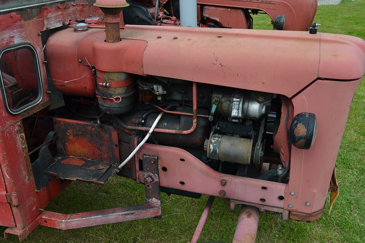
Field service begins before a wire fails: labels, branch boundaries, connector access and protected spare length determine how quickly a technician can isolate a fault. When developing from a used sample, we document damaged insulation, improvised splices, missing clips and non-original connectors rather than reproducing them blindly. Confirm the equipment serial range, option set, mating components and circuit intention before releasing a replacement. A physical sample may show geometry but cannot reveal every hidden material or software-dependent function.

Identify the machine variant

Model year, serial range and fitted options may change a visually similar loom.

Keep a controlled sample

Record uncertainty, confirm against drawings and freeze approved corrections before repeat orders.

Agricultural harness questions

Is this one universal tractor harness?

No. It is a category covering cab, engine, chassis, lighting, sensor and implement assemblies. Machine model, options, pin map, voltage and installation define the actual part.

Does an ISOBUS connector guarantee implement compatibility?

No. Mating hardware is only the physical layer. ISO 11783 network design, controller software, power allocation and the required AEF functions must be checked for the tractor and implement combination.

Can a worn sample be used to make a replacement?

It can establish some dimensions and interfaces, but damage, field repairs, hidden wire specifications and machine-option differences need separate confirmation before the first article is approved.

How is a sealed agricultural harness verified?

Routine electrical and visual checks are not a sealing qualification. Specify the mated connector system, installed condition, applicable test method, sample size and acceptance limit if ingress validation is required.

What do you need for a quotation?

Please send machine model and revision, wiring drawing or sample, connector part numbers and pin schedule, loads and protection, branch dimensions, exposure and movement zones, quantity, labels and requested inspection or validation.

Photo sources and licenses

PART NUMBER / INTERFACE / MATERIAL

Models, Part Numbers & Sourcing

Find a cable model or material part number, then send it for a custom replacement or original-part sourcing review.

Back to Top ↑

6 references · Search by brand or part number

Cable & Harness Models

Manufacturer-identified finished assemblies for this application.

  • PEAK-System

    IPEK-003009

    PCAN-Cable J1939, Type 1 DEUTSCH to D-Sub

    Custom compatible replacements · Original-parts sourcing

  • PEAK-System

    IPEK-003019

    PCAN-Cable J1939, Type 2 DEUTSCH to D-Sub

    Custom compatible replacements · Original-parts sourcing

  • PEAK-System

    IPEK-003014

    PCAN-Cable J1939, Type 1 DEUTSCH to 2 x D-Sub

    Custom compatible replacements · Original-parts sourcing

  • PEAK-System

    IPEK-003015

    PCAN-Cable J1939, Type 2 DEUTSCH to 2 x D-Sub

    Custom compatible replacements · Original-parts sourcing

  • John Deere

    BE32277

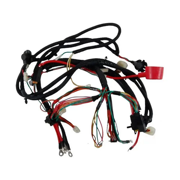
    Cab and Battery Wiring Harness for Non-ISOBUS Tractor

    Custom compatible replacements · Original-parts sourcing

  • John Deere

    AE50531

    2 Terminal Plug to 3 Terminal Socket Wiring Harness

    Custom compatible replacements · Original-parts sourcing

Selection & Project Review

01 Application Boundary

A tractor harness is a family of zone-specific assemblies rather than one universal part. Cab, powertrain, chassis and implement branches face different vibration, mud, spray, UV, temperature and service loads. An ISOBUS-shaped connector alone does not establish ISO 11783 communication or AEF function compatibility; controller software, bus topology, power supply and implement functions must also match.

02 Project Inputs

For quotation, provide machine make, model and revision, voltage, circuit and pin schedules, mating connector part numbers, loads and fusing, CAN/ISOBUS topology if used, branch lengths and installation photographs, movement and exposure zones, quantity, labels and the agreed inspection scope. A reference sample helps establish geometry, but undocumented repairs must be distinguished from the intended design.

03 Release Records

The approved drawing and first article freeze connector orientation, cavity map, branch datum, covering transitions, clips, service loops and test points. Routine continuity, shorts, dimensional and visual checks are recorded to the agreed plan. Sealing, vibration, flex, thermal and full-machine functional validation are separate project-defined tests; they are not implied by a passing wire map.

04 Interface Review

Confirm the exact mating interface, pin map, dimensions and installation orientation.

05 Sample Acceptance

Agree the sample configuration and electrical, mechanical or environmental checks required by the project.

06 Change Control

Record changes to materials, drawings and process instructions before repeat manufacture.

Send the part number, drawing or sample to confirm the replacement configuration and sourcing plan.

PROJECT REVIEW / CUSTOM MANUFACTURING

Custom Wire Harness Manufacturing in China

Custom wire harness manufacturing from our China factory, with OEM/ODM project support.

A sample, clear connector photos or a description of the equipment and required quantity is enough to start a review.

Discuss Custom Manufacturing & Sourcing

Start with a part number, drawing, sample or equipment requirement.

Information for an accurate quotation

When available, include drawings and BOM, connector and mating part numbers, pinout, wire length and gauge, branch layout, quantity and required tests. Materials, inspection scope and delivery are confirmed for each project.